Card shuffler 3
From DDL Wiki
(→Design for Assembly [DFA]) |
(→Product Function and Evaluation) |
||
| Line 68: | Line 68: | ||
''Step-by-Step Product Use'' | ''Step-by-Step Product Use'' | ||
| - | + | 1. Retrieve shuffler from storage location and place on playing table. | |
| - | + | ||
| + | 2. Place clear retaining shield into appropriate position through: | ||
::a. rest base on top of spring-loaded platform | ::a. rest base on top of spring-loaded platform | ||
| + | :::[[Image:Step 2a.png|thumb|none|150px|Step 2a]] | ||
::b. depress fully | ::b. depress fully | ||
| + | :::[[Image:Step 2b.png|thumb|none|150px|Step 2b]] | ||
::c. release ensuring retaining shield slots into guide clips | ::c. release ensuring retaining shield slots into guide clips | ||
| - | + | :::[[Image:Step 2c.png|thumb|none|150px|Step 2c]] | |
| - | + | 3. Load half of cards into each feeder tray. | |
| - | + | ::[[Image:Step 3.png|thumb|none|150px|Step 3]] | |
| - | + | ||
| + | 4.Depress bar labeled “push down to operate” until no cards remain in feeder trays. | ||
| + | ::[[Image:Step 4.png|thumb|none|150px|Step 4]] | ||
| + | |||
| + | 5.Lower and remove retaining shield. | ||
| + | ::[[Image:Step 5.png|thumb|none|150px|Step 5]] | ||
| + | |||
| + | 6.Enjoy your freshly shuffled cards. | ||
=List of Parts= | =List of Parts= | ||
Revision as of 23:06, 30 January 2014

Contents |
Executive Summary
Primary Stakeholders and Product Needs
Distributor Needs
Distributor needs are concerned with the ease and safety of transport.
- Packed with smallest possible box to save space
- Packed with rectangular box to stack efficiently
- Packed robustly enough to withstand bumps and slight drops
- Batteries either not included or shipped according to U.S. Department of Transportation
Retailer
Retailers have the same needs as distributors for stocking purposes, plus some needs unique to the seller of the product.
- Packaging is colorful and intriguing to costumers
Consumer
The product is primarily aimed at amateur card players who require a system for their home. Taking this into account, consumer needs are mainly related to portability, performance, maintenance and safety.
- Small
- Light
- Small table footprint
- Battery powered
- Shuffle quickly and thoroughly
- Minimal jamming
- Quiet
- Easy to load/unload
- Shuffle anywhere from 1 to 6 decks
- Work with brand new and used cards
- Long batter life
- Easily replaced batteries
- Easily fixed jams
- Robust
- Minimal Assembly
- Affordable
- Aesthetic product
- Safe to use and store
Product Function and Evaluation
Usage

Mechanical Function

Both sides of the card shuffler are mirrored and work independently. Their only connection is through the electrical circuit which closes once the bar is depressed. The following is a description of one independent side of the card shuffler.
The main mechanical function of the card shuffler comes from the motor/gearbox components. When the circuit is completed, the motor pinion turns the gearing system shown in figure 1. The pinion gear turns the first gear on the far right. This gear then translates its motion in two ways: 1) It directly rotates the agitator gear attached behind it on the same shaft 2) It translates its motion through the second gear to turn the third gear. The third gear is attached to a rubber wheel that grips a card from the feeder tray and slides it into the collection chamber. The agitation gear is a quarter gear that slightly protrudes above the feeder tray. This facilitates a steady flow of individual cards by vibrating the stack so that no cards stick together.
Upon entering the collection chamber, the cards encounter a routing surface (Part #adsf in Figure #adfasdf) which angles the cards downwards towards the base of the collection chamber. The base of the collection chamber sits on springs which compress as more cards are shuffled. This prevents the cards from flipping over on their way down the collection chamber by keeping the top of the stack close to the entrance of the chamber. Figure #adfs shows the platform of the collection chamber in its fully extended position; as cards stack in the collection chamber, the springs compress and the platform lowers.
Preliminary User Study
Step-by-Step Product Use
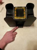
1. Retrieve shuffler from storage location and place on playing table.
2. Place clear retaining shield into appropriate position through:
- a. rest base on top of spring-loaded platform
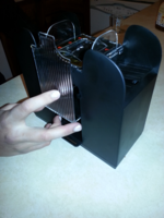 Step 2a
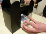
- b. depress fully
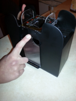 Step 2b
- c. release ensuring retaining shield slots into guide clips
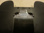 Step 2c
- a. rest base on top of spring-loaded platform


3. Load half of cards into each feeder tray.
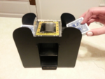 Step 3

4.Depress bar labeled “push down to operate” until no cards remain in feeder trays.
 Step 4

5.Lower and remove retaining shield.
 Step 5

6.Enjoy your freshly shuffled cards.
List of Parts
Design For Manufacturing and Assembly [DFMA]
Design For Manufacturing [DFM]
Successful DFM implementations:
- Mirrored design
- Identical design to previous model
- Slide-in battery contacts
- Drafted internal screw mounting posts + drafted card chamber
- Motor drives feeder + agaitator (only 1 motor per side)
- Almost exclusively injection molded plastic (easy to make)
- Gears, motors, fasteners can be COTS
- Loose tolerances
- Stickers and colored plastic remove need for paint
Potential Improvements:
- Riser for gear box unnecessary
- Outer casing 5 components, possible to make w/ less
- Not drafted support posts -> caused irregular finish
- Injection molds have complex features
Design for Assembly [DFA]
Successful DFA Implementations:
- 2 motor/gearbox system avoids complex transmission system
- Motors wired in series (less wires than parallel)
- Ultrasonic welding between parts
- Complex motor/gearbox combo can be independently assembled/tested
- All mechanical components operate without outer shell in place
- Screw posts have lip that function as guide pins for the enclosure and base
- Shuffler build bottom-up
- Loose tolerances allow for quick assembly
Potential Improvements:
- Screws could be replaced by snap-fit fixtures
- Gearbox stands add additional assembly steps
- Sticker requires careful placement to preserve aesthetics
- Spring attachment points used hand-melted rivets
Failure Mode and Effect Analysis [FMEA]
Design for Environment [DFE]
Team Members [TM]
Role:Rodrigo Bergamasco
Role:Allen Kim
Role:Alexander Kozhemiakov
Role:Angela Nawrocki
Role:Pranay Sharm
