Coffee grinder
From DDL Wiki
(Difference between revisions)
(→Team Members) |
(→Team Members) |
||
| Line 157: | Line 157: | ||
= Team Members = | = Team Members = | ||
| - | Phil Aufdencamp - | + | Phil Aufdencamp - DFE |
Justin Barsano - DFMA | Justin Barsano - DFMA | ||
| - | Kristen Hauser - | + | Kristen Hauser - User Study, General Organization |
Brian Tang - FMEA | Brian Tang - FMEA | ||
Revision as of 03:52, 1 February 2014
Contents |
Executive Summary
Primary Stakeholders and Product Needs
Product Function and Use
User Study
Mechanical Function
List of Parts
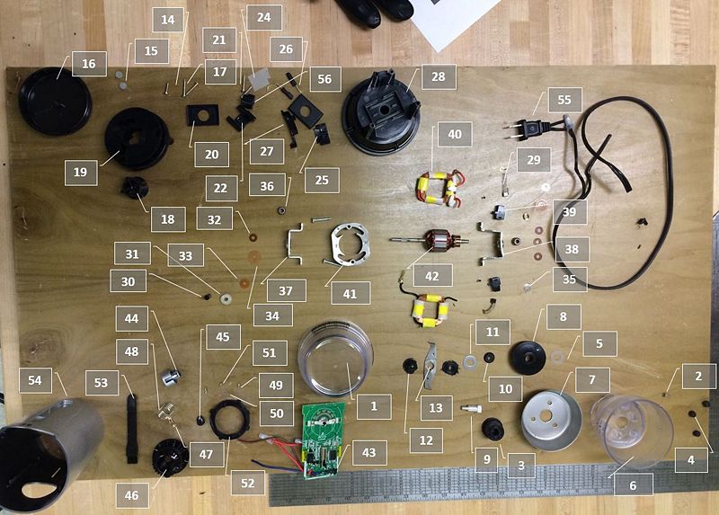
The following details the list of parts of a hands-free coffee grinder.
Bill of Materials
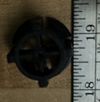
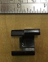
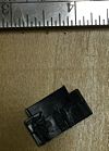
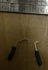
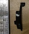
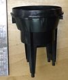
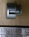
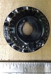
| Part Number | Name | Quantity | Mass (g) | Function | Material | Manufacturing Process/ Purchased Component | Image |
|---|---|---|---|---|---|---|---|
| Grinding Chamber Sub-Assembly | |||||||
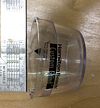
| 1 | Lid | 1 | 66 | Contains coffee | Plastic | Blow Molded | |
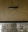
| 2 | Flat Head Screws | 3 | <1 | Cup to Scatter Shield | Steel | Catalog Purchase | |
| 3 | Female Drive Adapter | 1 | 6 | Provides Torque to Blade Assy | Plastic | Injection Molding | |
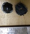
| 4 | Rubber Nipples | 3 | <1 | Vibration Isolation & Noise Reduction | Rubber | Die Cut | |
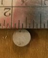
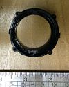
| 5 | Plastic Washer | 1 | <1 | Reduces friction of Blade Assy | Plastic | Catalog Purchase | |
| 6 | Cup | 1 | 46 | Provides References for Coffee Bean Measuring | Plastic | Injection Molding | |
| 7 | Scatter Guard | 1 | 15 | Contains Coffee Beans behind the Blade | Tin | Stamped | |
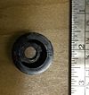
| 8 | Dust Shield | 1 | 3 | Separates the Grinding Chamber and the Drive Assy | Plastic | Injection Molding | |
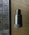
| 9 | Blade-Adapter Shaft | 1 | 2 | Transmits Torque from Part 3 to Part 13 | Plastic | Catalog Purchase | |
| 10 | Blade Gasket | 1 | <1 | Seals Blade Assy | Rubber | Injection Molding | |
| 11 | Blade Washer | 1 | <1 | Reduces friction of Blade Assy and Provides Axial Preload | Steel | Catalog Purchase | |
| Blade Sub-Assembly | |||||||
| 12 | Blade Hub | 1 | 2 | Connects blade to drive shaft | Plastic | Injection Molding | |
| 13 | Blade | 1 | 3 | Grinds Coffee | Stainless Steel | Stamped | |
| Cord Housing Sub-Assembly | |||||||
| 14 | Tamper Proof Screw | 1 | <1 | Connects cord housing assembly to main body | Steel | Purchased Part | |
| 15 | Rubber Foot Pad | 3 | <1 | Prevents Device from Slipping | Rubber | Stamped | |
| 16 | Cord Reel Container | 1 | 17 | Contains Cord While Wound | Plastic | Blow Formed | |
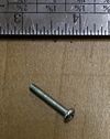
| 17 | Screw | 3 | <1 | Mates Part 19 to Part 28 | Steel | Purchased Part | |
| 18 | Power Cord Reel Center | 1 | 3 | Cord Capstan | Plastic | Injection Molded | |
| 19 | Power Cord Reel | 1 | 26 | Captures Cord | Plastic | Injection Molded | |
| 20 | Internal Motor Gasket | 2 | 3 | Seals Motor Components | Rubber | Injection Molding | |
| 21 | Screw For Part 22 | 2 | 1 | Mates Part 22 to Part 28 | Steel | Purchased Part | |
| 22 | Power Cord Retention Clip | 1 | 2 | Positively Retains The Power Cord Inside The Housing | Plastic | Injection Molding | |
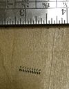
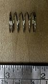
| 23 | Tiny Spring | 1 | <1 | Provides Preload to the Safety Mechanism | Steel | Purchased Part | |
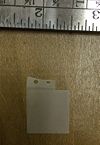
| 24 | Safety Paper | 1 | <1 | Reduces Abrasion of Safety Switch | Plastic | Stamped | |
| 25 | Electrical Switch Cover | 1 | 1 | Houses Electric Switch | Plastic | Injection Molded | |
| 26 | Electrical Switch Lead | 2 | 1 | Provides Current to Electrical Switch | Copper | Purchased Part | |
| 27 | Mechanical Switch | 1 | 1 | Actuates the Safety Switch | Plastic | Injection Molded | |
| 28 | Motor Housing | 1 | 47 | Secures motor to device | Plastic | Injection Molded | |
| AC Motor Sub-Assembly | |||||||
| 29 | Brushes | 2 | <1 | Provides Current to Commutator | Carbon | Electronic Component | |
| 30 | Motor Shaft Cap | 1 | <1 | Transmits Torque from Part 42 to Part ?? | Plastic | Injection Molded | |
| 31 | Shaft Insulator | 1 | <1 | Provides Mechanical and Electrical Insulation to the Shaft | Fiber | Stamped | |
| 32 | Spring Washer | 1 | <1 | Provides Axial Preload to locate the commutator with respect to the bushings | Copper | Purchased | |
| 33 | Small Brown Washers | 4 | <1 | Locates Part 42 Axially | Plastic | Stamped | |
| 34 | Large Orange Washers | 2 | <1 | Locates Part 42 Axially | Plastic | Stamped | |
| 35 | Small Metal Washers | 2 | <1 | Locates Part 42 Axially | Steel | Purchased | |
| 36 | Bearing | 2 | 2 | Locates Part 42 Radially | Steel | Purchased | |
| 37 | Brush Side Bracket | 1 | 17 | Locate Part 36 on Brush Side | Steel | Stamped and Bent | |
| 38 | Non-Brush Side Bracket | 1 | 16 | Locate Part 36 on Non Brush Side | Steel | Stamped and Bent | |
| 39 | Brush Housing | 2 | 1 | Constrains Part 29 | Plastic | Injection Molded | |
| 40 | Stator Coil | 2 | 13 | Provides Magnetic Poles | n/a | Electronic Component | |
| 41 | Steel Inductor Plate | 30 | 4 | Enhances Magnetic Poles | Steel | Stamped | |
| 42 | Rotor | 1 | 77 | Provides Motor Torque | n/a | Electrical Component | |
| 43 | Circuit Board | 1 | 28 | Assembly | Electrical Component | ||
| 56 | Male Drive Adapter | 1 | 15 | Plastic | Injection Molded | ||
| Knob Sub-Assembly | |||||||
| 44 | Power Button | 1 | 2 | Allows user to operate grinder | Plastic | Injection Molded | |
| 45 | Power Button Finger | 1 | <1 | Translate power button movement to connect circuit | Plastic | Injection Molded | |
| 46 | Knob | 1 | 8 | Allows user to adjust fineness of grind | Plastic | Injection Molded | |
| 47 | Circuit Board Connector | 1 | <1 | Connects fineness knob circuit | Copper | Stamped | |
| 48 | Power Button Spring | 1 | <1 | Returns power button after press | Steel | Purchased | |
| 49 | Knob Screws | 4 | <1 | Fastens knob sub-assembly | Steel | Purchased | |
| 50 | Detent Springs | 2 | <1 | Pushes ball bearings for discrete adjustment of knob | Steel | Purchase | |
| 51 | Detent Bearings | 2 | <1 | Allows for discrete adjustment of knob | Steel | Purchased | |
| 52 | Detent Housing | 1 | 2 | Contains detent components in knob | Plastic | Injection Molded | |
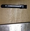
| 53 | Brush | 1 | 3 | Cleans coffee grinds | Plastic | Injection Molded | |
| 54 | Body | 1 | 74 | Houses inner components | Plastic | Injection Molded | |
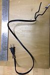
| 55 | Power Cord | 1 | Supplies electrical current from outlet to grinder | Assembly | Purchased | ||
Design For Manufacturing and Assembly (DFMA)
Failure Modes and Effects Analysis (FMEA)
Design for Environment (DFE)
Team Members
Phil Aufdencamp - DFE
Justin Barsano - DFMA
Kristen Hauser - User Study, General Organization
Brian Tang - FMEA
References
Dieter, George E., and Linda C. Schmidt. Engineering Design. 4th Edition. New York, NY: McGraw-Hill, 2009. Print.
