Fire extinguisher
From DDL Wiki
| Line 1: | Line 1: | ||
Automated fire extinguisher | Automated fire extinguisher | ||
| - | [[Image: | + | [[Image:FE full.jpg]] |
==Use of Product== | ==Use of Product== | ||
Revision as of 23:16, 23 September 2007
Contents |
Use of Product
Parts List
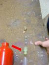
In order to gain a complete understanding regarding the functionality and operation of the fire extinguisher, the product must be dissected and each part analyzed. The following table reviews the results of dissection performed September 14.
DFX (Design for ‘X’)
The initial design step involved a product dissection and in-depth analysis to determine how the product was designed as it pertains to manufacture, assembly, usability, and the environment.
Design for Manufacture
Manufacturing processes were analyzed to determine cost and time necessary to produce the product.
Mounting Bracket: The mounting bracket is made of a single piece of injection molded plastic. Since it is not critical for this part to be made of a high level of precision, this method of manufacture is the cheapest and quickest. The part must clasp the neck of the canister and strap around the midsection to provide support when mounted on a wall or other horizontal surface.
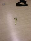
Safety Pin: The safety pin is a single piece of injection-molded plastic. The pin serves to prevent the fire extinguisher from being accidentally discharged. This plastic need only be strong enough to withstand the force exerted on it by a human hand squeezing the handle.
Canister: The main canister is manufactured by deep drawing a piece of aluminum. A sheet of aluminum is forced through increasingly smaller holes until it resembles a cylindrical canister. The top portion is then squeezed inwards to form the neck. The formed canister resembles a fuel bottle and is rated for a pressure of up to 300psi. This form of manufacture is the most widely used method across the industry and is the most cost and time effective way to produce a reliable pressure vessel.
Spring: The spring is manufactured by drawing stainless steel into a wire and coiling it to form a spring shape. This process allows for quick manufacture when in mass production. As the wire is drawn, it is wrapped and therefore the process is continuous.
Hose: The hose is made of a translucent plastic that is extruded into a hollow cylinder. The walls of the hose are thin, making the part cheap and easy to produce. This is effective because there are no net forces acting on the hose as the pressure in the canister is uniform.
Valve Pin: The valve pin is one of the more complicated parts to manufacture in the fire extinguisher assembly. Using a hot work method, the pin is first extruded to the diameter of the lower half. Then, the top is pressed inward to form the cone shaped section. In an automated setup, the notch details are cut out with the same method as would be used on a lathe. Production of this part is costly. A less expensive method would be to cast the part using destroyable molds. This method is likely not used due to the necessary precision of the part.
Top Assembly Gasket: The gasket is manufactured by injection molding a ring like shape from a piece of rubber. This process can be automated to enable inexpensive mass production.
Hose-Top Assembly Connector: To connect the hose to the top assembly, a separate piece is required. This piece is made of a translucent plastic by the method of injection molding. This piece is then placed on the hose and crimped into a permanent position.
Valve Pin Top & Bottom Gasket: Made via injection molding a rubber material into a ring. Creates a good seal between the valve and orifice.
Diffusing Nozzle: Alters flow of outgoing chemical by narrowing the cross sectional area. This device also disperses the flow outward. The nozzle is 7/16in. diameter and is then contracted down to 1/8in. to pressurize and disperse the flow. This part is made of a hard plastic via injection molding.
Design for Assembly
Design considerations affect the assembly process, determining the associated costs and time.
In general, the fire extinguisher was designed very well for assembly. There are very few parts, and the methods used to put them together don’t get any more complicated than screwing a piece into place.
One suggestion to simplify the assembly process would be to make the nozzle and top assemble out of one piece. This would eliminate then need to press the nozzle on.
On a similar thought of simplification, the hose and hose-top assembly connector could also have been made of a single piece. The current design did not allow this to happen because of differences in the method required to manufacture the two parts. A redesign to the hose-top assembly connector making the part simpler would allow for a one-piece design.
Design For Usability
Design decisions impact how easy a product is to use by the consumer.
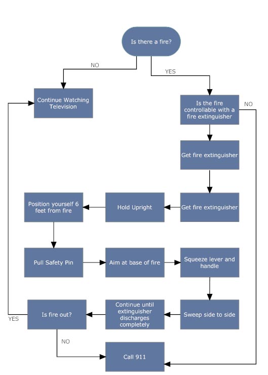
The simple design of the handle allows for ease of operation by the user. Without reading the instructions, the average user will instinctively be able to operate the extinguisher. The fire creates a sense of panic, to which most people will react by tensing up, or in the case of the fire extinguisher, squeeze.
Prior to this step, the user must locate and pull the safety pin. For this reason, the pin is a bright red, making it stand out from the rest of the assembly. This choice of color enables the user to quickly locate the pin and remove it.
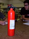
Since most users will not be aware of the weight difference between a full and empty extinguisher, the product is equipped with a gauge, telling you if the device is full or empty. The gauge is clearly labeled, with green markings for full (the go equivalent color) and red for empty.
Instructions are clearly outlined on the canister, to provide the user with a step-by-step guide to use the product. A potential improvement would be to make the drawings larger for ease of visibility.
Another part that our team flagged for improvement is the handle. The current design requires approximately 12lbs of force to depress the handle and discharge the contents. By increasing the length of the handle, the force required to operate would be reduced, making the product more accessible to individuals with below average hand strength.
Design for Safety
Safety of the user must be considered during the design process. For our product, user safety should be addressed by analyzing material strengths and probabilities of failure.
One major concern is the structural integrity of the canister, which is rated to 300psi. Since the assumed pressure of the tank is roughly 40% of this, the likely hood of a material failure leading to an explosion is extremely low. Increasing the safety factor would be costly and unnecessary.
The red safety pin adequately prevents accidental discharge. The pin is designed well because it is secure enough that it serves its purpose, but is not too difficult to remove to operate the device.
While the instructions tell you how to operate the device, some directions arrows on the actual parts might be useful to ensure proper device operation. For example, an arrow pointing in the direction that the device is intended to point would be useful.
FMEA
There are many possible ways for the fire extinguisher to fail. Most failures could leave the extinguisher completely inoperable. The biggest issues regard the structural integrity of the aluminum canister or problems with the plastic top triggering mechanism. Most failures would result from misuse or misinstallation of the extinguisher.
Below is a list of these failures and the ways in which they affect the overall performance of the product.
| Item & Function | Failure Mode | Effects of Failure | S | Causes of Failure | O | Design Controls | D | RPN | Recmd Actions | Responsibility & Deadline | Actions Taken | S* | O* | D* | RPN* | |
|---|---|---|---|---|---|---|---|---|---|---|---|---|---|---|---|---|
| Mounting Bracket | Extinguisher falls off bracket | Compromises structural integrity of the canister and triggering mechanism. | 8 | Canister not secured to bracket | 5 | Secure canister to bracket | 5 | 125 | Add strap to make sure canister is secured to bracket | Design Engineers | - | 5 | 5 | 5 | 125 | |
| Bracket falls off wall | Compromises structural integrity of the canister and triggering mechanism | 5 | Bracket not screwed securely to wall | 5 | Test mounting bracket on different types of walls | 3 | 75 | Treat motor axis to add strength | Design Engineers | - | 5 | 5 | 3 | 75 | ||
| Pressure Gauge | May not display proper reading. | Empty extinguisher could read as full. | 10 | Pressure from canister not correctly transmitted to gauge. | 2 | Test gauges by slowly discharging canister | 3 | 50 | Increase space around the pressure gauge in order to ensure that the gauge correctly reads the pressure in the canister | Design Engineers | - | 10 | 2 | 3 | 50 | |
| Safety Pin | Pin breaks and cannot be removed | If the pin cannot be removed, the extinguisher will not discharge | 10 | Pin is thin, may snap if not pulled out straight | 3 | Test strength of pin | 2 | 50 | Make pin thicker. Use stronger plastic. | Pin Manufacturer | - | 10 | 3 | 2 | 50 | |
Top Assembly
| Top handle breaks | Cannot depress pin to trigger the extinguisher | 10 | Extinguisher falls or is hit by an object | 1 | Test durability of top handle | 5 | 50 | Increase thickness of plastic. Use Stronger Plastic | Design Engineers | - | 10 | 1 | 5 | 50 | |
| Bottom Handle breaks | Uncomfortable to hold/use | 3 | Extinguisher falls or is hit by an object | 1 | Test durability of bottom handle | 5 | 15 | Increase thickness of plastic. Use Stronger Plastic | Design Engineers | - | 3 | 1 | 5 | 15
| ||
| Valve Pin | Does not seal properly | Could result in slow loss of pressure from the canister, leaving the extinguisher useless | 10 | Rubber gaskets may not fit on the pin correctly resulting in an ineffective seal | 3 | Test seals performance at large range of pressure | 2 | 60 | Find a better way to secure gasket to pin | Design Engineers | - | 10 | 3 | 2 | 60 |
|
| Canister | Over pressurized | Could result in unexpected rapid decompression, rendering the extinguisher useless and possibly exploding | 10 | Canister is over pressurized | 3 | Test canister to see its maximum pressure | 2 | 60 | Increase safety factor by increasing the maximum pressure rating of the canister | Design Engineers | - | 10 | 3 | 2 | 60 |
|
Quantitative Analysis
==
Headline text
==


