Hand crank radio
From DDL Wiki
Contents |
Executive Summary
Stakeholders and Product Needs
There are four main stakeholders concerned with this product: consumers, distributors / retailers, manufacturers and transporters (shipment). Each of the stakeholders have different needs as listed below.
Consumers
The Kikkerland Solar Radio Crank is directed toward household consumers who are concerned about their carbon footprint or natural disasters (which may cause extended power outages). Based on our user studies, these are some areas that consumers feel the radio can be improved on.
- Cheaper product price
- Clarity & loudness of radio
- Size
- Durability & reliability
- Efficiency of solar cell & crank (i.e. number of rotations to minutes of radio time)
- Ease of use
- Weatherproof
- Ease of tuning
- Better signal reception
- Fast shipping and efficient transport
Distributors / Retailers
For retailers and distributors, the following characteristics of the radio may come in handy.
- Efficient packaging for cheap & easy transport
- Safe packaging to protect the product functions
- Appealing packaging to display at the store
- Minimal waste packaging
- Product must be in demand
- Ease of storage (e.g. stackability)
- High demand
Manufacturers
The Kikkerland Solar Radio Crank should meet the demands of the customer while being produced at minimum expense, and hence earning the company a better profit margin. Below are some aspects that the manufactures want in their production of the radio.
- Less parts
- Common materials
- Easy assembly to reduce labor costs
- Automated assembly
- Standardized parts
- Reduce shipping costs
- Cheaper production costs
- High demand
Shipping / Transport
For ease of transports, these characteristics are important.
- Lightweight
- Ease of storage (e.g. stackability)
- Durability
- High demand (e.g. large shipment quantities)
Usage
How It is Used
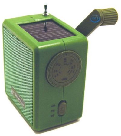
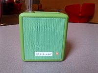
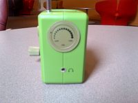
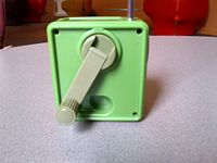
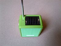
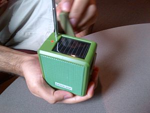
This radio requires neither a battery nor a power cord to function. For power, this radio possesses a small solar panel on its upper face as well as a hand crank on its side as shown in the figures below.
The solar panel allows the user to leave the radio exposed to direct sunlight and listen to their favorite station while the radio gathers solar energy. The hand crank is especially useful indoors, during nighttime, or in emergency situations where light is not directly accessible. The radio contains a dynamo generator that can store the energy created by manual-cranking and gathered from the solar panel in the 300 mAh/2.3 Ni-MH battery. Here are the steps to operate the dynamo solar radio:
- Rotate arm or expose radio to sun to generate energy
- 1 min cranking = 30 min radio play time
- 5 hours sunlight = 30 min radio play time
- Turn the On/Off/Volume dial
- Change frequencies by switching the AM/FM/WB switch
- Turn tuning dial to change stations
- Plug in headphones for headphone option
Radio Frequency Available:
- Fm Frequency Range: 87-108 MHz
- Am Frequency Range: 530-1600 kHz
- Radio Frequency Range: 149-186 MHz
User Studies
The portable hand-cranked radio seemed very easy to use. However, there were a few areas of design that must be changed. For instance, the resistance of the crank motion seems to be proportional to the speed of the cranking. The faster the cranking is, the more power is generated but the bigger the resistance becomes. There is a need to be able to find a balance point between resistance in the wheels and power generated from the crank and the solar panel.
While researching this product, there were a few common themes in the review of the product. They are as follow:
- Direct sunlight is needed for the panels to absorb sunlight efficiently
- Antenna for the radio goes straight up, it does not bend
- If you are using the product outside in a sunny day, you never have to crank for power as the solar panel itself will provide the radio with enough power
- On average, 1 minute of cranking gives approximately 15-25 minutes of playing time. Or, 100 turns of the crank is equal to approximate 10 minutes of audio
- The radio is small and light, it fits in the palm of your hand
From these comments, it can be concluded that the energy conversion either from mechanical to electrical, or from solar to electrical, is quite efficient. With a few tweaks, it may be possible to integrate this system with other daily life appliances to convert the rolling mechanical energy into electrical energy. A cheap and portable system to recapture the energy lost from a mechanical process in our daily life may present an interesting research and business opportunity. To achieve these goals for the design process, additional understanding and research on the product must be done.
Bill of Materials
Components
| Part Number | Name | QTY | Weight (g) | Function | Material | Manufacturing Process | Image |
|---|---|---|---|---|---|---|---|
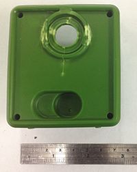
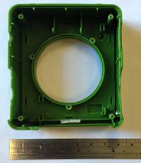
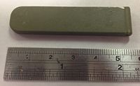
| 1 | Back Case | 1 | 31.2 | Holding the assembly together. Where the crank is attached | Plastic | Injection molding | |
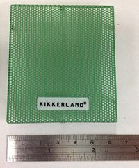
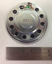
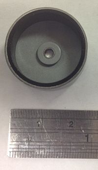
| 2 | Speaker Screen Mesh | 1 | 8.5 | Protecting the speaker from physical disturbance | Steel | Stamping | |
| 3 | Front Case | 1 | 25.5 | Holding the speaker | Plastic | Injection molding | |
| 4 | Speaker Plate | 1 | 8.5 | Housing the magnet to create the vibration | Steel | Stamping | |
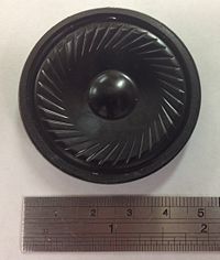
| 5 | Speaker Cone | 1 | Less than a gram | Vibrating to produce the sound | Plastic / Polymer | Stamping, Vacuum forming | |
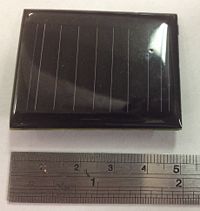
| 6 | Solar Panel Assembly | 1 | 5.7 | Converting solar energy to electrical energy | Monocrystalline Silicon Wafer, Plastic, Lead, Rubber, Copper | Soldering, Lithography, Masking, Depositing, Etching | |
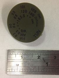
| 7 | Radio Station Tuner Indicator | 1 | Less than a gram | Indicating the frequency of the radio | Plastic | Injection molding, Printing for labels | |
| 8 | Generator Magnet | 1 | 2.8 | Producing magnetic field to generate electricity | Metal Alloys | Pressing, Heating, Annealing, Finishing, Magnetizing | |
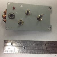
| 9 | Generator Plate | 1 | 14.2 | Holding gears and generator in place | Steel | Stamping | |
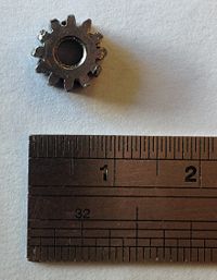
| 10 | Gear 4 | 1 | Less than a gram | Connecting the generator to other gears | Steel | Hobbing | |
| 11 | Gear Shaft | 1 | Less than a gram | Connecting the generator to gear 4, Mounting gear 4 | Steel | Cold rolling | |
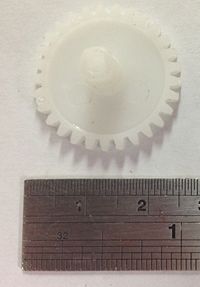
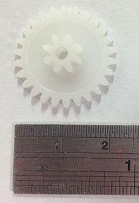
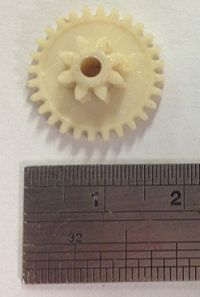
| 12 | Gear 1 | 1 | Less than a gram | Translating crank motion | Nylon (self-lubricating) | Injection molding | |
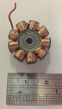
| 13 | Generator | 1 | 11.3 | Generating electricity from rotation | Copper, Steel | Stamping, Layering, Coiling | |
| 14 | Gear 2 | 1 | Less than a gram | Translating crank motion | Nylon (self-lubricating) | Injection molding | |
| 15 | Generator Shell | 1 | 5.7 | Holding the magnet in place | Steel | Stamping | |
| 16 | Gear 3 | 1 | Less than a gram | Translating crank motion | Nylon (self-lubricating) | Injection molding | |
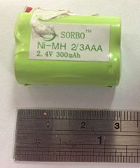
| 17 | Battery Pack | 1 | 14.2 | Storing energy for radio operation | Plastic, Copper, Rubber, Nickel Metal Hydride | Advanced manufacturing technique | |
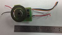
| 18 | Volume and Power Circuit Assembly | 1 | 8.5 | Control the volume and turn on the radio | Plastic, Lead, Copper, Rubber, Semi Conducting Materials, Polymer / Wax | Soldering, Lithography, Masking, Depositing, Etching | |
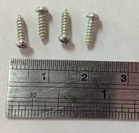
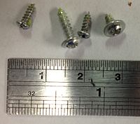
| 19 | Outside Screw | 4 | Less than a gram | Hold the two cases together | Stainless Steel | Cold heading, Thread rolling | |
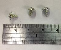
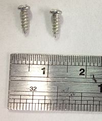
| 20 | Speaker Screw | 3 | Less than a gram | Attaching the speaker to the front case | Stainless Steel | Cold heading, Thread rolling | |
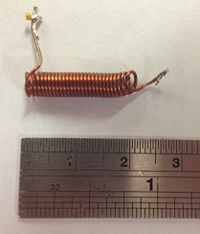
| 21 | Antenna's Solenoid | 1 | Less than a gram | Generating the magnetic field required for radio signal | Copper | Coiling, Hardening | |
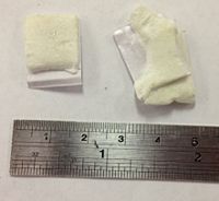
| 22 | Solar Panel Pad | 2 | Less than a gram | Stabilize the solar panel | Foam / Paper / Polymer | Polymerization forming | |
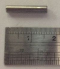
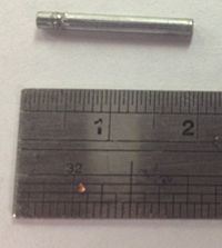
| 23 | Crank Dowel | 1 | Less than a gram | Connecting crank shaft and collar | Steel | Cold rolling | |
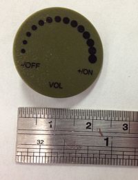
| 24 | On / Off / Volume Indicator | 1 | Less than a gram | Adjust speaker volume | Plastic | Injection molding, Printing for labels | |
| 25 | Antenna | 1 | 8.5 | Enhancing signal reception | Stainless steel, Aluminum, Brass | Cold drawing, Die drawing | |
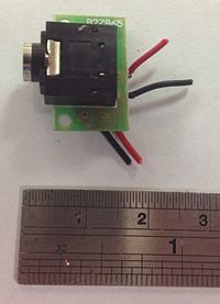
| 26 | Headphone Jack Assembly | 1 | Less than a gram | Connecting headphone to the speaker | Copper, Plastic, Rubber, Steel, Lead | Soldering, Lithography, Masking, Depositing, Etching | |
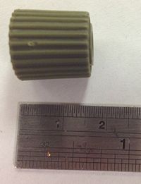
| 27 | Crank Knob | 1 | 2.8 | Making it easier to turn the crank | Plastic | Injection molding | |
| 28 | Crank Shaft | 1 | 2.8 | Increasing the lever arm | Plastic | Injection Molding | |
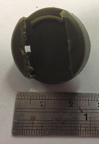
| 29 | Crank's Attachment Disk | 1 | 2.8 | Connecting crank shaft to the gear | Plastic | Injection Molding | |
| 30 | Hand crank collar | 1 | Less than a gram | Stabilizing the rotational movement of the crank | Steel | Stamping | |
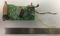
| 31 | Tuning Microprocessor Assembly | 1 | 22.7 | Tuning the radio frequency (FM / AM / WB) | Plastic, Lead, Copper, Rubber, Semi Conducting Materials, Polymer / Wax | Soldering, Lithography, Masking, Depositing, Etching | |
| 32 | Generator screws | 4 (3 different kinds) | Less than a gram | Holding generator to the case and the gear system | Stainless Steel | Cold heading, Thread rolling | |
| 33 | Headphone Screws | 2 | Less than a gram | Holding headphone adapter | Stainless Steel | Cold heading, Thread rolling | |
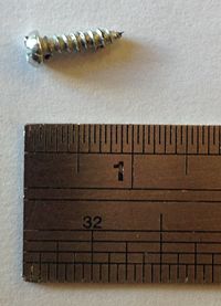
| 34 | Antenna Screw | 1 | Less than a gram | Holding the antenna to the case | Stainless Steel | Cold heading, Thread rolling | |
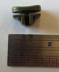
| 35 | Crank-Gear Collar | 1 | Less than a gram | Connecting the crank's collar and the gear | Plastic | Injection molding | |
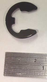
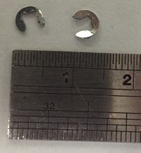
| 36 | Gear Collar Clamps | 2 | Less than a gram | Holding the gears together | Steel | Stamping | |
| 37 | Frequency Range Switch Knob | 1 | Less than a gram | Indicating if the frequency range of the radio (FM / AM / WB) | Plastic | Injection molding | |
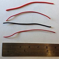
| 38 | Cable | 1 | Less than a gram | Connecting electrical components | Copper, Rubber | Drawing through rubber die | |
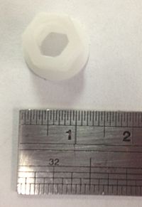
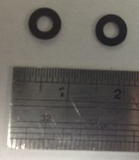
| 39 | O Ring | 2 | Less than a gram | Mounting the magnet on top of the generator | Plastic | Stamping | |
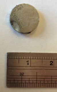
| 40 | Speaker Magnet | 1 | 2.8 | Controlling the vibration of the speaker to generate the sound | Metal alloys | Pressing, Heating, Annealing, Finishing, Magnetizing | |
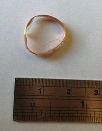
| 41 | Speaker Coil | 1 | 8.5 | Allowing the speaker screen to vibrate | Copper | Rolling |
Assembly Diagram
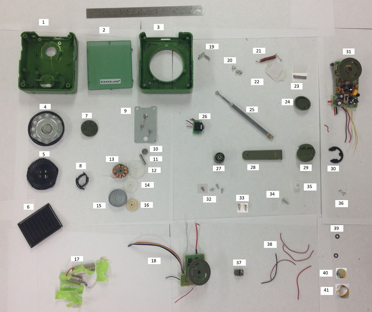
The parts cannot be assembled back after taking them apart due to the wire connections that need to be severed to separate the integrated circuits. The assembly procedure can, however, be described as follows:
- Assemble the gear box with the generator by attaching it to part 9. (Gear box consists of part 10, 12, 14, 15, 16, 36 and Generator consists of part 8, 11, 13, 15, 39).
- Assemble the speaker by putting the magnet (part 40) on the speaker plate (part 4) and then attach the speaker coil (part 41) to the speaker cone (part 5). Attach the two assemblies together.
- Connect the integrated circuits together using the cables with their corresponding indicator (part 6, 7, 17, 18, 24, 26, 31, 37, 38).
- Connect the antenna and the solenoid with the integrated circuit (part 21, 25, 31, 34, 38).
- Assemble the hand crank (part 23, 27, 28, 29, 30, 35).
- Insert hand crank assembly to the back case (part 1).
- Connect the generator and gear assembly to the back case (using part 32).
- Connect the speaker assembly to the front case (part 3 using part 20).
- Attach the integrated circuits to the front case and fasten the headphone jack using part 33, attach the solar panel using pads (part 22).
- Attach the front case to the back case using part 19.
- Lastly insert the speaker screen mesh (part 2) to the front case.
Assembly Diagram
Mechanical Function
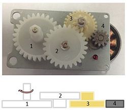
The mechanical aspect is comprised of the generator-crank system. The basic structure is as follows (please refer to figure 6 for reference):
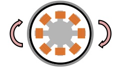
The hand crank contains a handle that’s rigidly attached to a shaft, which is then mounted to gear 1. The purpose of the handle is to make it easier for the user to “crank” and thereby input torque into the gear system to be amplified. The gear system composes of 4 gears, with gear 1 being the input torque gear, gear 4 being the output torque gear, and gears 2 and 4 being the angular velocity magnification gears. Moreover, gear 4 is connected to a shaft that rotates the generator shell. The idea behind the gear system is that with one full “crank” of the handle, the gears will magnify this one rotation into 10 or 20 full rotations of gear 4. This drastically increases efficiency in rotating the generator shell to generate electricity. According to Faraday’s Law of Induction, the rotation of the generator shell generates a magnetic field, which then generates a current that can be stored and used by the hand crank radio.
The faster the rotation, the more current that is generated; therefore, the gear system is designed to have a higher power and lower speed input from the user that is to be converted into a lower power, but higher speed into the generator. Therefore, when the user wishes to play the ratio, he must manually turn the crank in order to generate the magnetic field that would in turn generate electric current which powers the hand crank radio.
Design for Manufacturing and Assembly (DFMA)
The main objective of Design for Manufacturing and Assembly (DFMA) analysis is to come up with various improvements geared towards simplifying the manufacturing and assembly process. Some important considerations may include part count, material selection, production volume, tolerances, etc.
This hand crank radio consists of 41 parts and assemblies as shown in the section above. The majority of the non-metal parts are made out of plastic or rubber through injection molding or stamping. These are pretty efficient methods of manufacturing non-metal components for mass production. The metal components, on the other hand, are made out of various materials including steel, aluminum, metal alloys, and many others. Depending on the use and the shape of the metal components, the manufacturing processes range from cold rolling, stamping, lithography, etc.
Some efforts have been made to simplify the design for the ease of manufacturing and assembly. These methods include:
- Bent tabs on the speaker screen makes it easy to assemble and enables it to be attached without additional parts.
- Most gears are made out of self-lubricating nylon, with standardized size and materials designed to minimize friction.
- Most of the non-metal components are made with injection molding. By changing the mold, a standard injection molding can potentially produce all of the non-metal components.
- The outer case are made with the same dimension allowing them to share similar features and enabling them to be fastened with each other easily.
- A lot of the control knobs are integrated. For instance, the on/off and volume controls are integrated in a single indicator, reducing the part count and simplifying the design.
- Parts with little need of tight tolerances are made out of plastic through injection molding, avoiding the need to scrutinize dimensions during the manufacturing process.
- Most of the non-metal parts are made through injection molding without the need of any secondary manufacturing process.
- Gears are injection molded in the same color for ease of coordination and the outer case is injection molded in green for aesthetic and environmental appeal (i.e. the radio is environmentally friendly, suggested by it's "greeness").
- Threaded holes eliminate the need of nuts and washers, minimizing the part count and ensuring fast assembly.
- Most of the electronics come in sub-assemblies which can be mass produced by other factories, allowing the manufacturer of the radio to specialize in assembling the radio together.
- Although the front case and back case look very similar, they are very easy to differentiate from one another.
- Plastic sockets with different sizes and champfers indicate where to attach which electrical assemblies on the cases.
Some improvements can be made in the following areas:
- There are a lot of screws with various sizes. Standardized screws will make the assembly process simpler and faster.
- The various circuit boards can be combined into one circuit board, minimizing part count and simplifying the assembly.
- The gear assembly seems complicated and difficult to disassemble due to space and volume constraint.
- The metal gear was pressed fit in. This procedure requires high accuracy and low tolerance.
- The wires connect circuit assemblies on both sides of the cases making it difficult to disassemble if there is anything wrong.
- Snap fits can be used instead of screws in some cases.
Failure Modes and Effects Analysis (FMEA)
Design for Environment (DFE)
Manufacturing
Use
End of Life
DFE Conclusions
Mechanical Analysis
Team Member Roles
Oscar Chahin: FMEA, Mechanical Analysis, User Study
Evan Gates: DFE, Stakeholders, DFE-IOC
Kartik Goyal: Bill Of Materials and Diagram, Usage, User Study, Mechanical Function
Huan (Steve) Qin: DFMA, DFE-IOC
Andre Sutanto: Wikipage editor, Bill of Materials, Stakeholders
References
Images taken from:
Figure 1: www.amazon.com/Kikkerland-Dynamo-Solar-Crank-Emergency/dp/B0017S4C26/ref=sr_1_2?ie=UTF8&qid=1346370017&sr=8-2&keywords=
