Hydraulic jack
From DDL Wiki
(→Mechanical Function) |
(→Mechanical Function) |
||
| Line 173: | Line 173: | ||
=== Mechanical Function === | === Mechanical Function === | ||
| - | The jack is made up of a series of concentric cylinders each of which is pressurized and holds differing amounts of hydraulic fluid. When the handle is inserted into the pump mechanism and moved up and down, fluid is pumped from a reservoir in the outer cylinder into the space in the bottom of the inner chamber, pushing the ramrod shell upward. This fluid is kept inside the inner cylinder by a high-pressure valve consisting of a check valve and | + | |
| + | |||
| + | |||
| + | The jack is made up of a series of concentric cylinders each of which is pressurized and holds differing amounts of hydraulic fluid. When the handle is inserted into the pump mechanism and moved up and down, fluid is pumped from a reservoir in the outer cylinder into the space in the bottom of the inner chamber, pushing the ramrod shell upward. This fluid is kept inside the inner cylinder by a high-pressure valve located in the base of the jack, consisting of a check valve and a debris filter to keep unwanted solids from breaking the seal created by the ball bearing. The jack can be released by loosening the valve screw at the jack’s base, thus allowing the fluid to return to the outer cylinder until the valve screw is tightened again. This release of fluid will then lower the ramrod shell, lowering the car and allowing the jack to be removed. The ramrod also has a section that can be unscrewed, providing extra length to the mechanism. | ||
Daniel Mark | Daniel Mark | ||
Revision as of 23:57, 31 January 2014
Contents |
Executive Summary
Daniel Tabrizi
Stakeholder Needs
Daniel Tabrizi
Usability Study
Daniel Tabrizi
Assembly
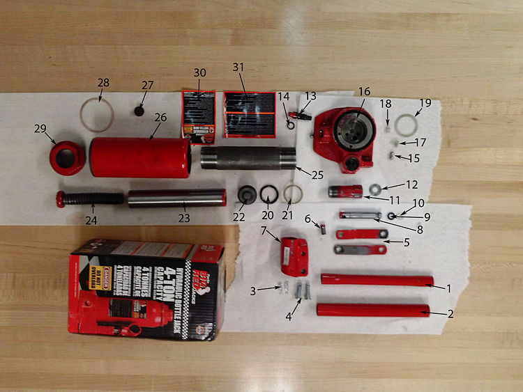
The following is an exploded view of the hydraulic jack. The parts each number corresponds to are listed below the picture and in the Bill of Materials section.
1. Inner Handle
2. Outer Handle
3. Alligator Clip
4. Pins
5. Pump Connector Rod
6. Link Connector Screw
7. Pump Handle Housing
8. Pump Rod
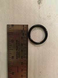
9. Pump O-Ring
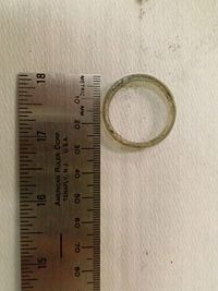
10. Pump Plastic Ring
11. Pump Housing
12. Pump Housing Washer
13. Valve Screw
14. Valve Screw O-Ring
15. Valve Ball Bearing
16. Base
17. Plastic Bumper
18. Plastic Fluid Filter
19. Base Plastic Washer
20. Ramrod Rubber O-Ring
21. Ramrod Plastic O-Ring Retainer
22. Ramrod Base
23. Ramrod Shell
24. Extender Screw
25. Inner Chamber
26. Outer Cylinder
27. Rubber Plug
28. Large Plastic Cap Ring
29. Outer Cylinder Screw Cap
30. English Warnings
31. Alternate Language Warnings
Daniel Mark
Bill of Materials
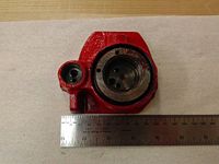
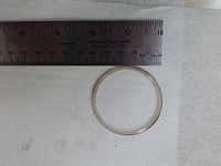
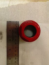
The following is a list of the 32 parts that make up the hydraulic bottle jack. Most pieces are made of steel, that has been shopped in some way, usually on a mill or a lathe. The non steel parts are either rubber or plastic and are purchased or injection molded. The table can be sorted by Part Number, Quantity, Weight, Material, and Manufacturing Process.
| Part Number | Name | Quantity | Weight (g) | Function | Material | Manufacturing Process | Image |
|---|---|---|---|---|---|---|---|
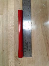
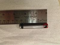
| 1 | Inner Handle | 1 | 78 | Inner handle piece, used to pump fluid | Painted steel | Bent, Welded | |
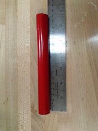
| 2 | Outer Handle | 1 | 134 | Outer handle piece, used to pump fluid | Painted steel | Bent, Welded | |
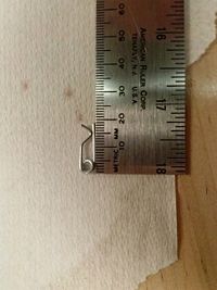
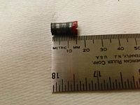
| 3 | Alligator Clip | 2 | <1 | Used to hold Pins (#4) in place | Aluminum | Purchased | |
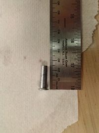
| 4 | Pin | 2 | 7 | Used to hold pump structure together | Steel | Purchased | |
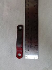
| 5 | Pump Connector Rod | 2 | 25 | Connects Pump Handle Housing (#6) to Base (#16) | Painted steel | Stamped | |
| 6 | Link Connector Screw | 1 | 5 | Connects Pump Connector Rods (#5) to Pump Handle Housing (#7) | Painted steel | Riveting | |
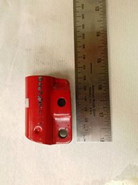
| 7 | Pump Handle Housing | 1 | 98 | Connects handle (#1&2) to Pump Rod (#8) | Painted steel | Stamped, Bent, Welded | |
| 8 | Pump Rod | 1 | 42 | Moves up and down to pressurize the jack | Painted steel | Automated Lathe Process, Drilled | |
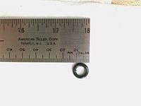
| 9 | Pump O-RIng | 1 | <1 | Creates a pressure seal for the pump | Rubber | Purchased | |
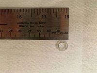
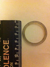
| 10 | Pump Plastic Ring | 1 | <1 | Holds the Pump O-RIng (#9) in place | Plastic | Purchased | |
| 11 | Pump Housing | 1 | 74 | Limits the Pump Rod (#8) motion to 1D | Painted steel | Automated Lathe Process, Threaded | |
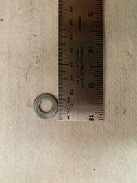
| 12 | Pump Housing Washer | 1 | 1 | Provides separation between the base and the bottom of the Pump Housing (#11) | Steel | Purchased | |
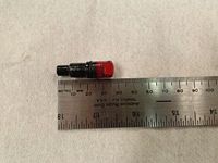
| 13 | Valve Screw | 1 | 18 | Allows for release of pressure in jack | Painted steel | Automated Lathe Process, Threaded, Stamped | |
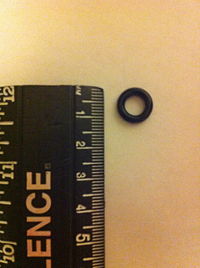
| 14 | Valve Screw O-RIng | 1 | <1 | Creates pressure seal around the Valve Screw (#13) | Rubber | Purchased | |
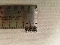
| 15 | Valve Ball Bearing | 3 | 1 | Creates or releases liquid seal allowing for flow between chambers | Steel | Purchased | |
| 16 | Base | 1 | 1049 | Holds entire jack together, houses the various valves in the jack | Painted steel | Cast Steel, Automated Mill Process, Threaded | |
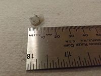
| 17 | Plastic Bumper | 1 | <1 | Holds Valve Ball Bearing (#15) in place | Plastic | Injection Molded | |
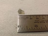
| 18 | Plastic Fluid Filter | 1 | <1 | Filters debris during liquid flow | Plastic | Injection Molded | |
| 19 | Base Plastic Washer | 1 | <1 | Seals base of Inner Chamber (#25) | Plastic | Purchased | |
| 20 | Ramrod Rubber O-Ring | 1 | <1 | Creates pressure seal around Ramrod Shell (#23) | Rubber | Purchased | |
| 21 | Ramrod Plastic O-Ring Retainer | 1 | 1 | Holds Ramrod Rubber O-RIng (#20) in place | Plastic | Purchased | |
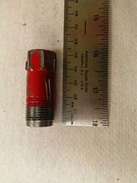
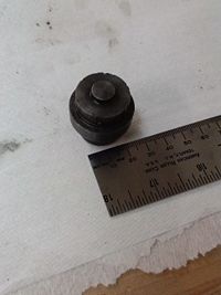
| 22 | Ramrod Base | 1 | 98 | Keeps liquid out of Ramrod Shell (#23) and prevents sticking to Base (#16) | Steel | Automated Lathe Process | |
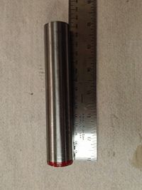
| 23 | Ramrod Shell | 1 | 310 | Moves up and down lifting and lowering anything on the jack | Steel | Automated Lathe Process, Threaded | |
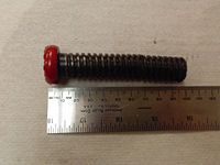
| 24 | Extender Screw | 1 | 176 | Allows for extra heigh to be reached by the jack | Steel | Automated Lathe Process, Threaded, Riveted | |
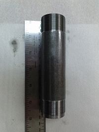
| 25 | Inner Chamber | 1 | 314 | Constrains Ramrod Shell (#23) to 1D motion | Steel | Automated Lathe Process, Threaded | |
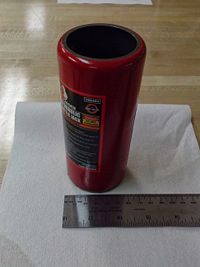
| 26 | Outer Cylinder | 1 | 405 | Houses liquid | Painted steel | Stamped, Bent, Welding | |
| 27 | Rubber Plug | 1 | <1 | Allows for initial filling of jack with hydraulic fluid | Rubber | Purchased | |
| 28 | Large Plastic Cap Ring | 1 | <1 | Prevents rubbing between Outer Cylinder Screw Cap (#29) and Outer Cylinder (#26) | Plastic | Purchased | |
| 29 | Outer Cylinder Screw Cap | 1 | 160 | Caps jack and prevents pressure leak | Painted steel | Cast Steel, Automated Lathe Process, Drilled, Threaded | |
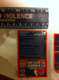
| 30 | English Warnings | 1 | <1 | Provides warnings in English | Paper | Printed | |
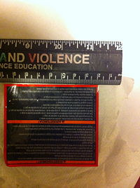
| 31 | Alternate Language Warnings | 1 | <1 | Provides warnings in Spanish and French | Paper | Printed |
Daniel Mark
Product Functionality
Step-by-Step Instructions
To raise:
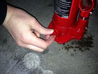
- Turn valve screw clockwise to tighten it and create a pressure seal
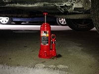
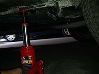
- Place jack under car and turn extender rod until it reaches the bottom of the car
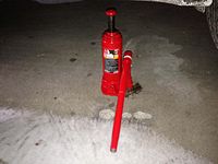
- Insert handle into pump handle housing
- Raise and lower handle to pump up car
To lower:
- Turn valve screw clockwise
- Twist down extender rod
- Pull jack out from under car
Mechanical Function
The jack is made up of a series of concentric cylinders each of which is pressurized and holds differing amounts of hydraulic fluid. When the handle is inserted into the pump mechanism and moved up and down, fluid is pumped from a reservoir in the outer cylinder into the space in the bottom of the inner chamber, pushing the ramrod shell upward. This fluid is kept inside the inner cylinder by a high-pressure valve located in the base of the jack, consisting of a check valve and a debris filter to keep unwanted solids from breaking the seal created by the ball bearing. The jack can be released by loosening the valve screw at the jack’s base, thus allowing the fluid to return to the outer cylinder until the valve screw is tightened again. This release of fluid will then lower the ramrod shell, lowering the car and allowing the jack to be removed. The ramrod also has a section that can be unscrewed, providing extra length to the mechanism.
Daniel Mark
Design for Manufacturing and Assembly (DFMA)
Derek Lessard
Failure Modes and Effects Analysis (FMEA)
Gloriana Redondo
Design for Environment (DFE)
Melanie Jasper
Team Member Roles
All
References
All
