Ice cube maker
From DDL Wiki
Contents |
Ice cube maker
Basic introduction information.
How on earth do we get the "contents" box?
Mode of Operation
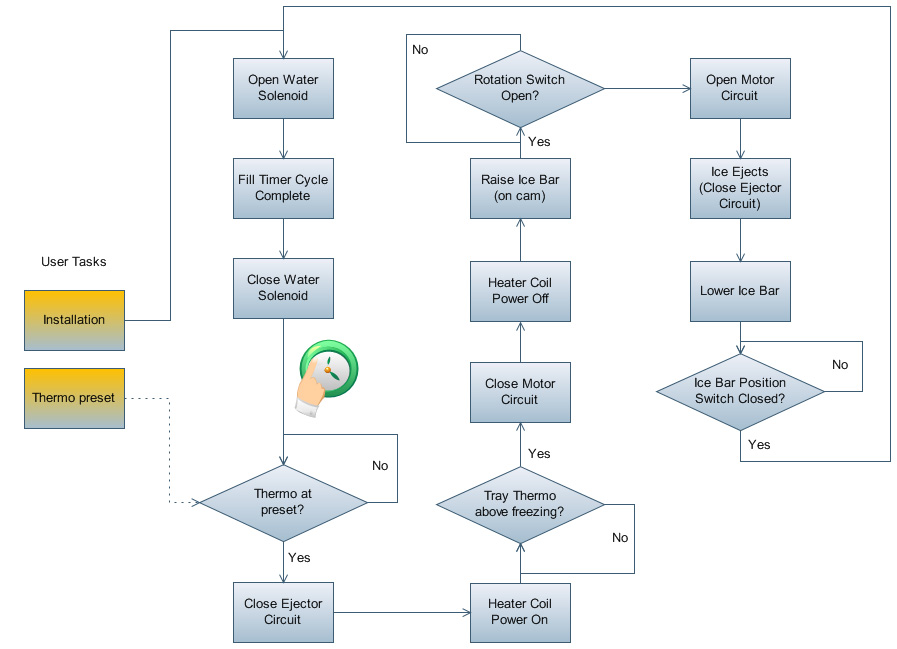
The automatic ice maker system functions on a looping mechanical/analog circuit algorithm. The entire system (showed graphically below) is synchronized and stepped by a central timing cam. This cam is assembled so that three electric switches are touching the cam, and are activated and deactivated as the AC motor revolves through the "program". According to external research, the default temperature that the ice temperature thermocouple is activated is 9 degrees Fahrenheit. The following is a flowchart outline of the freezing program.
Bill of Materials
| Part # | Part Name | Qty | Function | Weight (Ounces) | Material | Manufacturing Process | Photo |
|---|---|---|---|---|---|---|---|
| 01 | Outside Cover | 1 | Protect machinery | 2 | PVC | Injection Molded | |
| 02 | Inside Cover | 1 | Protect machinery | 2 | PVC | Injection Molded | |
| 03 | Ice ejector gear | 1 | Connect the ice ejector to the switches | 0.1 | Plastic | Injection Molded | |
| 04 | Ice ejector timing shaft | 1 | Connect ice ejector gear to the ice ejector | 0.4 | Plastic | Injection Molded | |
| 05 | Ice ejector drive shaft | 1 | Transfer torque from the motor to the ice ejector | 0.1 | Plastic | Injection Molded | |
| 06 | Ice ejector | 1 | Rotate to push ice out of tray and into bin | 1 | Plastic | Injection Molded | |
| 07 | Outer plate | 1 | Separate and support the mechanical components from the electrical wires | 3 | Steel | Blanked and machine finished | |
| 08 | Switch | 3 | Synchronize the mechanical elements | 0.2 | Plastic, Steel | Purchased | |
| 09 | Motor | 1 | Power the ice maker | 6 | Steel, other | Purchased | |
| 10 | Arm | 1 | Senses when ice box is full to stop ice maker | 0.1 | Steel | Machine bent | |
| 11 | Arm Spring | 1 | Transfers arm motion to CAM | <0.1 | Steel | Purchased | |
| 12 | CAM | 1 | Stops ice ejector shaft from rotating | 3.2 | Steel | Cast and finish machined | |
| 13 | Thermocouple | 2 | Switch on/off power to the heater | 0.1 | Various | Purchased | - |
| 14 | Thermopaste | enough | Transfer heat | <0.1 | Thermal Paste | Purchased | |
| 15 | Heater | 1 | Heats tray to allow ice to be removed | 3 | Aluminum, Stranded Electrical Wire, Plastic | Purchased | |
| 16 | Ice Tray | 1 | Holds water while it freezes to become ice | 14.5 | Metal, Unknown | Casted | |
| 17 | Ice shield | 1 | Keeps ice cubes from rotating back into the tray, guides ice cubes into bin | 1.1 | Plastic | Injection Molded | |
| 18 | Ice Bin | 1 | Collects and stores ice cubes | 16.5 | PVC | Injection Molded | |
| 19 | Electrical Wires | 6 | Transfer electricity | <0.1 | Plastic & Stranded Electrical Wire | Purchased | |
| 20 | Electrical Wire Cap | X | Joins wires together and covers the connection | <0.1 | Plastic | Molded | |
| 21 | Water Inlet | 1 | Collects water and guides it into the ice tray | 0.5 | Plastic | Injection Molded | |
| 22 | Screws and bolts, nuts, & washers | 17 | Attach parts and keep them in place | <0.1 | Steel | Purchased |
**Note: Some assemblies and parts were not disassembled in order to avoid destroying the parts.
LCA
The Economic Input-Output Life Cycle Assessment (EIO-LCA) website, www.eiolca.net, contains data on the most common contributors to greenhouse gases, toxic releases, and energy usage from industries and sections of those industries. Although there was not a category that specifically fit our product, our ice maker fit best in the category of “Household refrigerator and home freezer manufacturing.” The simulation pretended that an additional $1 million had been spent in this industry, then we examined the how much extra greenhouse gases would be released into the atmosphere. If the product were typical for its sector, the following table displays how many greenhouse gases would be emitted in to the atmosphere by spending an extra $1 million:
| Sector | GWP MTCO2E | CO2 MTCO2E | CH4 MTCO2E | N2O MTCO2E | CFCs MTCO2E |
|---|---|---|---|---|---|
| Total for all sectors | 881. | 671. | 62.0 | 12.7 | 136. |
| Power generation and supply | 231 | 228 | 0 | 0 | 2. |
| Industrial gas manufacturing | 161. | 46.1 | 0 | 0 | 115 |
| Truck transportation | 54.3 | 53.5 | 0.083 | 0.746 | 0 |
| Household refrigerator and home freezer manufacturing | 36.3 | 36.3 | 0 | 0 | 0 |
| Waste management and remediation services | 27.2 | 4.30 | 22.9 | 0.033 | 0 |
| Plastics material and resin manufacturing | 18.8 | 18.8 | 0 | 0 | 0 |
| Oil and gas extraction | 18.1 | 3.04 | 15.1 | 0 | 0 |
In manufacturing our ice maker, about a third of the greenhouse gasses emitted come from the creating the power necessary to create it. The metal necessary to create a freezer or refrigerator explain why Iron and steel mills are the next highest sector to output greenhouse gases. Our product, an ice maker has a very low metal content, so this does not make sense in the context of our specific product. Transportation of materials and finished product requires a significant amount of energy. The sector in which our product appears contributes a smaller amount of greenhouse gases, but the waste from the process contributes and even smaller amount. After these sectors we find that manufacturing the plastic components contributes as well as the process of extracting oil and gas (used in both the power generation and the creation of the plastics).
The best method for reducing the ecological impact of our product is to decrease the amount of power used in the manufacturing process. Making this more efficient could potentially cut down significantly the amount of greenhouse gases emitted. Additionally, if the transportation of parts and finished product were made more efficient this would be better for the environment.
Design for Manufacturing and Assembly
The design of the system has been developed for easy and cost efficient manufacturing and assembling. Over all, there are three major families of components installed on the system: metals, plastic and accessories.
The most notable (and heavy) component of the system is the metal ice cube tray. The material selection of this part has allowed it to exhibit high thermal conductivity properties. The part has been highly engineered for metal injection molding efficiency. The process has been identified as injection molding based on the existence of notable ejector pin scars that remain on the part. On the core side of the mold, identified as the top side where the ice sits, are appropriate draft angles and wall thicknesses to be compatible with the metal injection molding process. This piece has a limited number of side actions, and thus is a remarkable example of an efficient injection molded component.
Also a significant metal component is the tray sensor bar, but this was not molded, but rather is a bent aluminum extrusion that is assembled by threading the entire length of the bar through the outer wall side panel. The angles of bends were chosen appropriately so this would be possible.
The plastic components of this assembly also are mostly injection molded. The side panels and outer assembly, as well as the gears and brackets, made with white ABS plastic and are created with high precision molding processes which made it a possibility to apply finely detailed trademark and identification labels inside the mold.
The accessories and wiring all consist of off-the-shelf components. The wiring is done with 12-gauge wire to allow for safe AC 110v handling, and the wire nuts are also off-the-shelf. The electric switches are all the same model, built from a third-party company, which greatly reduced engineering and assembly costs for the manufacturer of the assembly. The heating coil is constructed by bending a pre-made heating coil, which seems to have been made by an extrusion process of a selectively electricity conducting material.
The majority of the assembly process is simplified by accurately and strategically placed mounting and bracketing locations on the white ABS walls of the assembly. The assembly order most likely prioritized the wiring last, as the wire nut layout seemed to be the final thing connecting multiple sub-assemblies.
Mechanical Analysis
Thermal FEA Analysis
We used an FEA thermal analysis to find that it takes approximately 5.50 hours for an ice cube to freeze in an aluminum tray. We used FEA analysis so that we can set a baseline for our future calculations. This will allow us to compare our material choices and ice cube shape to the design that we evaluated.
Analysis Methods
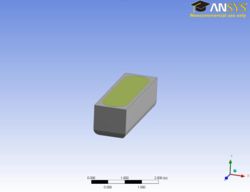
ANSYS Workbench was used to perform the analysis. A Transient Thermal simulation was performed on the model illustrated below (Fig. 1).
The analysis made several assumptions but found a fairly reasonable answer compared to what we were able to get with simple analytical solutions. First, we modeled just one ice cube in one tray. This could have been expanded but computational time would have increased greatly. We assumed that because of the high conductivity of aluminum that the heat transfer would be dominated by the surroundings and each ice cube would have only a small effect on adjacent cubes. Second, we assumed material properties consistent with those found in Heat Transfer, 9th Edition (J. P. Holman). Third, we assumed that the thermal properties of water remain the same as it freezes. Details of the simulation can be seen below (Table 1).
Table 1 – Transient Thermal Analysis Details
| Mesh Details | |
| Number of Elements | 17008 |
| Number of Nodes | 34039 |
| Transient Analysis Details | |
| Minimum Step Size | 10 |
| Maximum Step Size | 100 |
| Initial Conditions | |
| T∞ (°C) | -16.10 |
| T0,water (°C) | 22.00 |
| T0,air (°C) | -16.10 |
| T0,tray (°C) | 22.00 |
| Results | |
| Ice Freezing time (hours) | 5:33 |
| Computation time (hours) | 0:38 |
Results
This analysis gives a good estimate of the time that it takes for our evaluated design to freeze. Even more importantly the analysis allows us to easily import our models and compare our design before building a prototype. This will allow us to validate our design before implementing it.
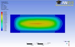
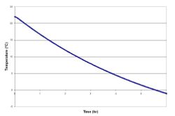
Below is an illustration (Fig. 2) that shows the temperature distribution at the moment that the ice cube becomes completely frozen. Another illustration (Fig. 3) shows the maximum temperature with respect to time.
Major Stakeholders and Needs
- Customer
- need
- need
- Dogs
- need
- need


