Inkjet Printer Notes Spring 2007
From DDL Wiki
Notes/Others
This section serves as our preliminary analysis information data base as of 02/12/07.Parts:
1.
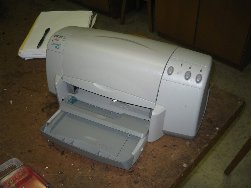
Printer
2.
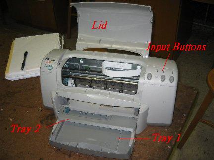
Lid/Paper Tray 1/ Paper Tray 2/ Input Buttons
Lid: prevents dust, allows ink replacement & paper adjustment
Paper Tray 1: holds pre-printed paper in straight position
Paper Tray 2: holds printed paper
Input Buttons: lets users input basic commands
Design Potential: *none
3.
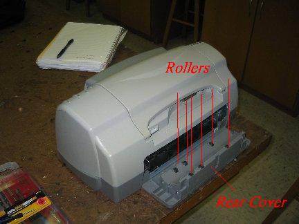
Rear Cover(w/ 6 rollers)
Rear Cover: The 6 rollers located on it assist the paper movement inside of the printer
Design Potential: It might be one of the potential location for our rear slot (for CD or other hard materials).
4.
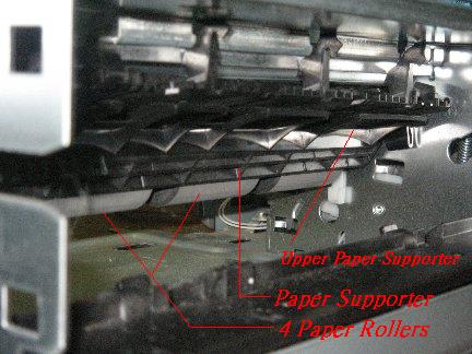
Upper Paper Supporter/Paper Supporter/Paper Rollers
Upper Paper Supporter: holds the printing paper in the y-direction
Paper Supporter: supports the printing paper upward
Paper Rollers: are the main rollers for paper movement
Design Potential: The two supporters need to be repositioned to create enough vertical space for the insertion of materials like CD.
5.
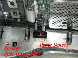
Springs/ Rear Upper Plate/ Paper Feed Sensor
Springs: acts as an simple shock absorber for the interior supporters
Rear Upper Plate: serves as the provider of opposite force on the Springs against the interior paper supporter; wirings attached on top
Paper Feed Sensor: senses the paper right before being printed
Design Potential: All three components will be repositioned to generate space for rear slot.
6.
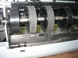
Rear Paper Roller
Rear Paper Roller: rolls the paper into the actual printing process
Design Potential: It might be another target for repositioning to create vertical space; it might have to be adjusted to work with materials that are much thicker than paper.
7.
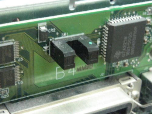
Lid Sensor
Lid Sensor: senses the opening and closing of the lid to trigger the movement of other interior components such as the cartridge
Design Potential: *none
8.
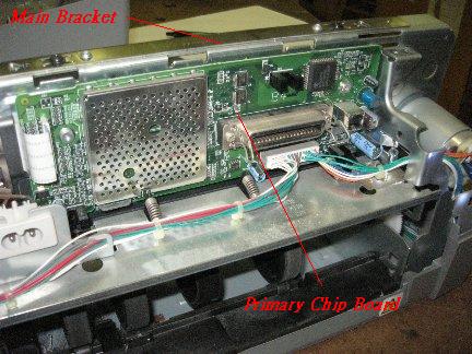
Main Bracket/ Primary Chip Board
Main Bracket: holds all the other major components in place, including the brackets for holding the motor and rear supporters
Primary Chip Board: responsible for input/output/power signals; connects to the main bracket
Design Potential: It will be relocated for the parts under it to be lifted up for additional vertical space
9.
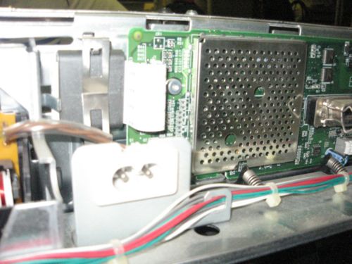
AC Power Supply Input
AC Power Supply Input Takes in 120V AC and supplies it to the power supply of the printer to be converted into DC for the circuit board to use
Design Potential: None
10.
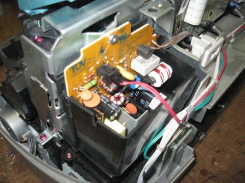
Power Supply
Power Supply: Converts the voltage supplied by the Power Supply Input from AC to DC
Design Potential: None
11.
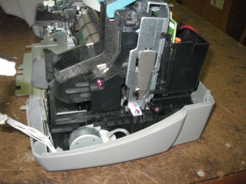
Inkjet Cleaner Unit
Inkjet Cleaner Unit: Responsible for keeping the head of the inkjet cartridge clean in between operations to prevent the hardening of ink and jamming of the cartridge
Design Potential: None
12.
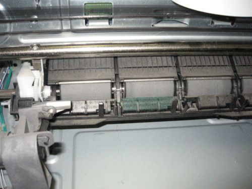
4 Paper Rollers
4 Paper Rollers: Responsible for moving the paper during the printing process
Design Potential: May need relocation to adapt to different page thicknesses
13.
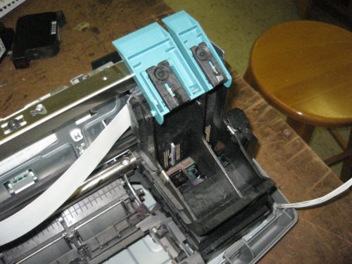
Inkjet Cartridge Craddle
Inkjet Cartridge Craddle: Holds the Inkjet Cartridge and transports it during the printing process
Design Potential: None, it will operate in the same fashion after redesign
14.
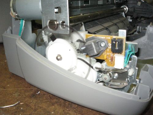
Paper Roller Encoder Gear
Paper Roller Encoder Gear: Sends information to an encoder (not visible) so that the printer knows how far the paper has traveled inside the printer
Design Potential: Physically the part will remain the same, but will need correction in the printing software to accommodate longer sheets of paper
15.
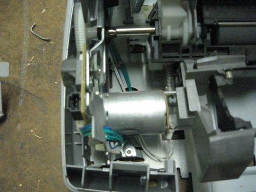
Paper Roller Motor
Paper Roller Motor: Supplies the mechanical energy to the paper rollers so that they can move
Design Potential: We intend to leave this part the same but we may need to replace with a higher torque motor in order to move heavier sheets of paper
16.
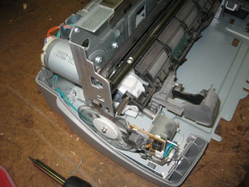
Inkjet Cartridge Craddle Motor
Inkjet Cartridge Motor: Supplies mechanical energy to the Inkjet Cartridge Craddle so that it can move
Inkjet Cartridge Encoder Strip: Allows the Inkjet Cartridge Craddle encoder to determine its position laterally across the paper.
Design Potential: None
17.
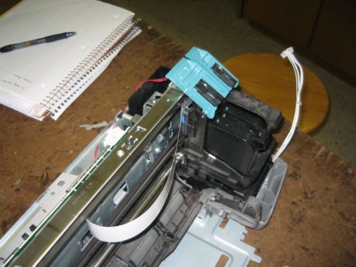
Print Cartridges
Print Cartridges: These cartridges hold the ink and the jets which place the ink on the paper.
Print Cartridge Slots: The slots which hold the cartridges can be seen in this view. The aqua-colored tabs at the top flip down to secure the cartridges in the slots.
Main Vertical Support: The main vertical support can be seen in this picture. It is a metal plate that is secured between two other supports which are in-turn stamped into the base plate. The support is the metal bar that comes up from the bottom left.
User Input Wires: The white bundle of wires at the right of the picture is the connection to the buttons on the top cover of the printer.
Design Potential: *none
18.
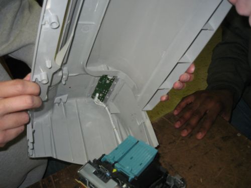
Inside of Top Cover
Print Cartridge Slots: The tabs which hold the print cartridges in can be seen in the locked position here.
User Input Wires: The white bundle of wires which was unplugged in the previous picture can be seen here plugged into the circuit board containing the user interface buttons.
Design Potential: *none
19.
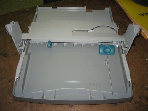
Paper Tray
Paper Tray: This tray holds the paper before and after it has been printed. The lower section holds blank paper ready to be printed, the upper tray holds the paper after it has gone through the rollers and been printed on.
Letter Feed: The slot in the top tray can be used to feed envelopes and other irregularly sized paper into the rollers.
Paper Placement Tabs: The two aqua tabs are used to keep the paper stacked neatly and in place for the rollers. These tabs can be moved in or out depending on what size paper is put into the tray.
Design Potential: *none
20.
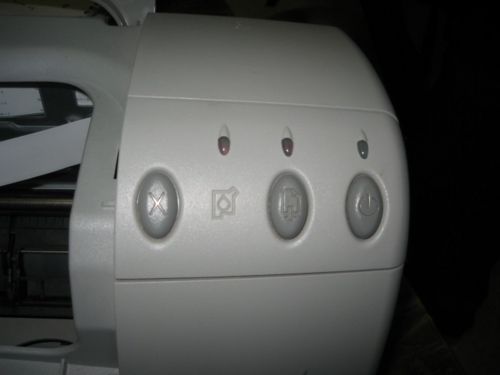
User Input Buttons
Cancel Button: The left-most button is the "Cancel" button. It cancels the current print job.
Paper Feed Button: The middle button is the "Paper Feed" button. This button feeds through any paper that has stopped part way in the rollers. It also must be pressed to reset a print job if there was a paper jam in the middle.
Power Button: The right-most button is the "Power" button. It does just what it says, it turns the power on or off. It is not a "hard" switch though (i.e. it won't turn the printer off without feeding any paper through the rollers first or returning the print cartridges to their docking position).
Design Potential: Possibly make the buttons more functional and less obscure.
21.
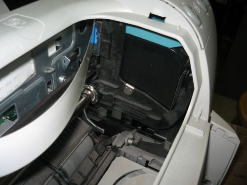
Print Cartridges in Docking Position
This is a picture of the print cartridges and slots in their docking position. When the printer is off or not in use they move to a protected position under the user buttons. The cartridges become locked in this position so that they are not damaged while the printer is not in use. The ribbon cable connecting the cartridges to the main processing circuit board can also be seen in this picture.
Design Potential: *none
22.
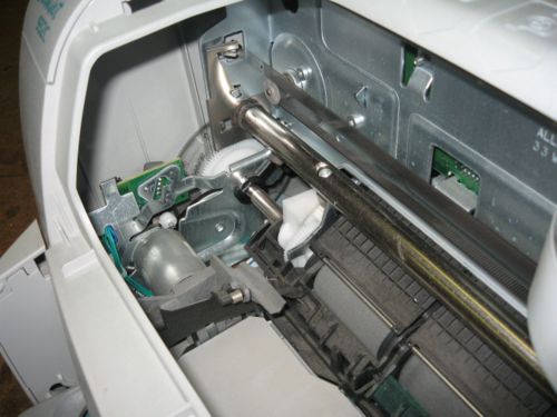
Roller Gears and Motor
In this picture one of gears which turns the rollers can be seen as well as the plastic disk which has the radial lines used by the encoder to determine the roller movement. The motor which controls the rollers can also be seen as well as the circuit board with the encoder and motor controller. The guide rail and linear encoder ribbon can be seen coming from the bottom right. The ribbon is used by an encoder on the print cartridge mechanism to determine its left-to-right position along the paper.
Design Potential: *none
