Lawn Mower Analysis
From DDL Wiki
(→Symbols and Equations) |
(→Conclusion) |
||
| Line 99: | Line 99: | ||
= Conclusion = | = Conclusion = | ||
| + | In conclusion, our project is the SHit MOFO | ||
| + | |||
= Implementation = | = Implementation = | ||
Revision as of 23:32, 10 November 2008
Contents |
Executive Summary
When deciding upon the basis of our Mechanical Analysis, we realized it was prudent to analyze an aspect of our product that dealt with user safety. We originally wanted to determine shearing forces of certain connections/attachments, or perhaps deflections and stresses upon the beams composing our product. This was to make the most appropriate material choices and thicknesses, but after consulting specialists in the Carnegie Mellon Machine Shop, we discovered that we were very limited to the material choices we could make due to weight and cost restrictions. Therefore, we elected to determine the static reaction forces on our product caused by the weight of our mechanism's platform with the lawn mower secured upon it. We have come up with a design that is anticipated to function as proposed while addressing key concerns such as weight, packaging, manufacturing, and material cost. The ensuing report consists of the purpose of our analysis, a list of the assumptions considered when performing the analysis, a list of the equations used and their symbols, and our conclusions obtained with our strategies for implementation.
Purpose of Analysis
The purpose of this analysis is to provide an overall factor of safety for the mechanism. It is crucial to predict the maximum forces encountered on the system in order to compensate with proper material choices and/or force-reducing apparatuses. We've chosen to implement a pulley system in our product to provide a more direct lifting force on the platform, while reducing the tension encountered in the winch. We plan to examine the magnitude of the reduction in the cable tension, the overall static forces of the system, and verify that the standard sizes of our mechanism's components will be sufficient and optimal for our design. This will ensure a safer and more durable product for the user, which consequently prevents any hazardous occurrences and regrettably, potential lawsuits.
Assumptions
- We will be assume that all bodies connected by welds are to be considered one single body.
- We will ignore the weight of the hardware and delrin rollers. We will assume that their weights are insignificant when compared with the weights of the steel tubing and steel plate.
- Ignore vibrations and resonance effects due to driving.
Symbols and Equations
| Description | Symbol | Value | Quantity |
|---|---|---|---|
| Weight of grate | G | 6 | 1 |
| Weight of bottom steel tube | S1 | 6.3 | 2 |
| Weight of lawnmower | W | 150 | 1 |
| Weight of ramp | Wr | 4.4 | 2 |
| Weight of bracket 1 | Wb1 | 2.5 | 1 |
| Weight of bracket 2 | Wb2 | 2.5 | 1 |
| Weight of vertical steel tube | S2 | 7.5 | 1 |
| Weight of bracket 3 | S2 | 1.8 | 2 |
| Weight of roller | R | 0.05 | 4 |
| Weight of L brackets | Wl | 0.74 | 4 |
| Length 1 | L1 | 17.5 | |
| Length 2 | L2 | 5 | |
| Length 3 | L3 | 3 | |
| Length 4 | L4 | 3 | |
| Length 5 | L5 | 3 | |
| Length 6 | L6 | 6 | |
| Roller radius | Rr | 1 | |
| Tension in cable | T | 196.66 |
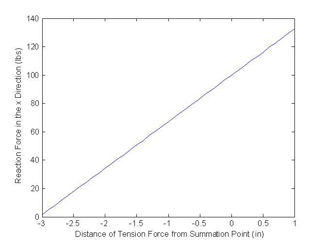
This graph shows the effect on the reaction force of moving the cable from the winch side to the plate side. One inch on the x-axis represents the cable lifting the bracket at pin that holds the rollers on the winch side. Negative three inches represents the cable lifting the bracket at the pin that holds the rollers on the plate side. We see that by placing the cable on the winch side, as we had originally planned, the reaction force in the x direction is 132.68 pounds. This causes a tremendous amount of shear in the vertical steel beam. To fix this problem we shifted the cable to the other side of the vertical beam using a pulley system. The reaction force in the x direction is reduced to 1.57 pounds and the shear effects are greatly reduced.
Conclusion
In conclusion, our project is the SHit MOFO

