Lawnmower carrier
From DDL Wiki
(→Mechanical Analysis) |
(→Prototype Documentation) |
||
| Line 62: | Line 62: | ||
== Prototype Documentation == | == Prototype Documentation == | ||
| + | Throughout the design process, we constructed three prototypes to physically analyze our design and improve upon it. These prototypes were essential to obtaining a high-quality functional final prototype and design. | ||
| + | '''Prototype I''' | ||
| + | The blueprint of our first prototype was surprisingly similar to that of our final prototype. It was constructed primarily out of wood, and was intended to demonstrate the lifting method of our product. The prototype consisted of a platform, pulley system, hand crank (to simulate a winch), and a clamping piece. We noticed with this prototype that it was quite difficult to actually lift the platform, which gave us ideas for improvement upon the pulley system and material choices. | ||
| + | |||
| + | '''Prototype II''' | ||
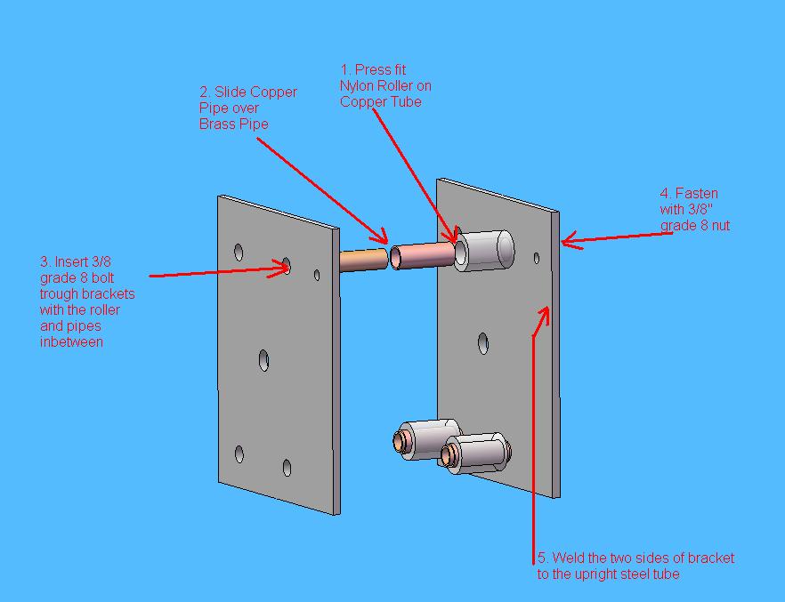
| + | Our second prototype was constructed using the base of Prototype I, but we incorporated the new pulley system that we had designed since our first prototype. This prototype was intended to demonstrate the ease of lifting with the application of this new pulley system. As opposed to having a pulley located on the winch-side of the device and lifting it from this side, we chose to place a pulley at the top of the device and lift the mower from the platform-side of the device. We also incorporated some new material choices, including the delrin rollers, which resulted in a smoother lifting of the platform. | ||
== Design Process == | == Design Process == | ||
Revision as of 21:45, 9 December 2008
Contents |
Lawn Mower Carrier
Overview
The purpose of this project was to select a product and determine an innovative way to improve it. Our product is a self-propelled lawnmower. We did some market research, which included speaking to people at a lawnmower repair shop. We saw early on that people had a problem transporting their mowers, and we determined that we were going to design a mechanism that makes it easier to move a mower between locations. The design that we came up with was a mechanical lift that slides into a standard trailer hitch. Through the design process, we built multiple prototypes, each time improving our design until we decided on the design for our final prototype. After constructing our final prototype and doing user testing we were able to determine changes that we would make for future designs. We also saw that our product could be used to transport not only lawnmowers but also personal electric scooters, bicycles, and a variety of other things. In the end we were able to create a product that would sell for more than half the price of our competitors and attack a wider market than we had originally expected. This is good evidence that there is a need for this product and we believe, if produced on a large scale, it would sell.
Market Analysis
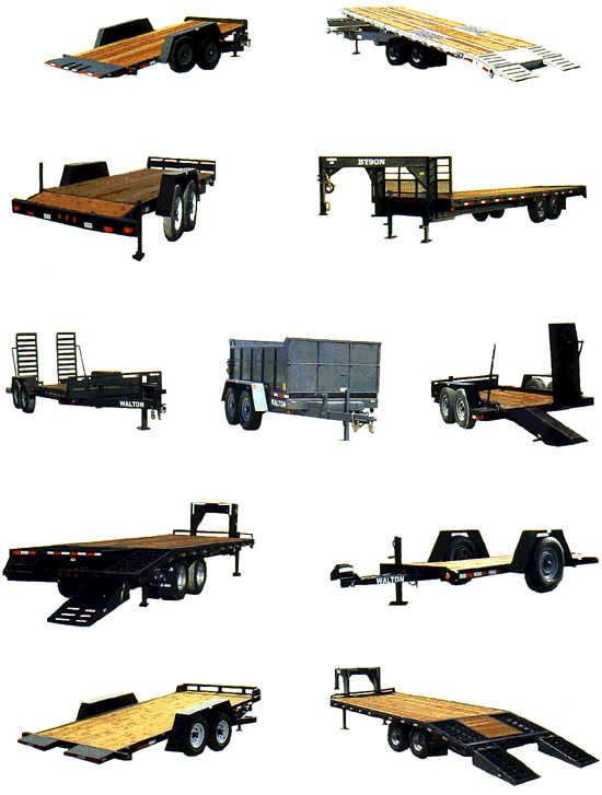
When first examining and dissecting our product, we intended on modifying the lawn mower in a way that would improve its usability, functionality, or performance. We wanted to improve the actual product so that it could better serve the user. Our potential ideas for improvement included a remodeled and ameliorated suspension system to allow for a more even lawn cut, or perhaps a blade speedometer to warn the user if the blades were dropping below an indicated stall-out speed. However, after performing market research and analysis, we realized that it would be difficult to improve upon a product that countless designers had spent time inventing. We spoke with some local retailers, service repairmen, and even our group member Alex, who had cut lawns independently for eleven years. We determined that one of the most significant issues with the lawn mower wasn't necessarily the mowing, rather the transportation of the mower itself. Several people that we spoke with commented on how dirty, labor-intensive, and time-consuming this process could be, especially if the user did not have an appropriate vehicle for transportation. Therefore, we chose to explore the market of trailer hitch attachments that could serve to transit a lawn mower. After examining the market for trailers and the sort, we realized that there wasn't really a product that was convenient for the independent lawn-mowing businessman. One can see from the photo below that the majority of the trailers are much too cumbersome and expensive for a non-commercial entrepreneur.
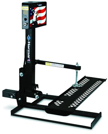
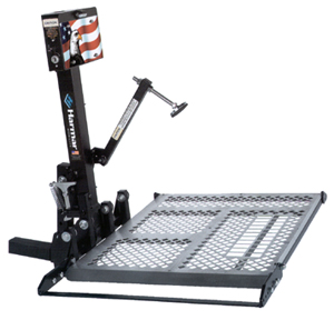
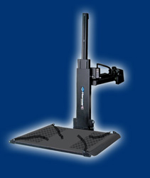
The trailers above range anywhere from $1,000-$5,000 in price and several of them are not appropriate for your average vehicle. We also researched the prices and designs of mobility scooter lifts for more comparison. A variety of this type of lift can be seen in the images below:
The scooter lifts were very similar to the idea we had in mind for our lawn mower carrier lift, yet they were still more expensive than what we predicted. These lifts usually cost anywhere from $1,000-$3,000, which is a significant amount more than our desired market price for the lawn mower lift. Our goal was to create a product that could be easily assembled onto a vehicle, and then easily removed as well. From this research and analysis, we determined that we could create a product that incorporated designs from both of the aforementioned compared products, but one that would cater to both commercial and independent business-owners. After constructing the prototype of the lawn mower carrier lift, we concluded that the cost of manufacture was right at the budget of $500. In order to determine the profitability of this product, one must analyze the methods of production. We could choose to mass produce the lift or produce it on a smaller scale that would entail custom ordering. Mass production would result in a much lower materials and parts cost because ordering them on a large scale significantly decreases their cost. The manufacturing methods for mass production, including stamping, robotic welding, and injection molding, are much cheaper because there is more automation and minimal human labor is required. Using this type of production and considering material costs and the manufacturing costs, the estimated cost of our product is around $250. This would result in a great level of profitability, because the market shows that we could sell the lift for at least $500. Small-scale production would result in less profit because it would much more expensive to produce the product due to an increase in the material and manufacturing costs. If this were the case, the market would allow us to sell our product close to $600, but production cost would approach this, resulting in smaller profitability. Therefore, mass production is the optimal method of production for our design.
Design Documentation
Design Analysis
House of Quality
Quality Function Deployment (QFD) was employed to benchmark our product against existing competitors in today's market. This process allows us to gain a deeper understanding of the benefits/disadvantages of our product within the marketplace and the relationship between the customer's requirements and quality characteristics of the lift. We chose to compare our product to a general utility trailer and mobility scooter lift in the House of Quality (HOQ) below:
| Error creating thumbnail: convert: unable to open image `/ux0/websites/wiki.ece.cmu.edu/wiki/virtual-hosts/ddl/images/House_of_Quality.jpg': No such file or directory @ error/blob.c/OpenBlob/2882. convert: no images defined `/ux0/websites/wiki.ece.cmu.edu/wiki/virtual-hosts/ddl/images/thumb/House_of_Quality.jpg/500px-House_of_Quality.jpg' @ error/convert.c/ConvertImageCommand/3235. |
Through the application of this process along with this diagram, we can obtain several conclusions about our product as compared to the others. Our product does not surpass the bench marked products in many of the assessed categories, but it exceeds in very important customer requirements: low cost, minimal weight, ease of assembly, and usability. We believe that these categories constitute a marketable product.
Mechanical Analysis
Since our prototype is made mainly of steel it is important to analyze the forces in key components to ensure safety. The purpose of this analysis will be to show the reaction forces in the rollers when the lift is in the elevated position. To perform this analysis we will have to make several assumptions. First, we will assume that there is no tension in the cable and that all the weight is on the pin. This is the worst case scenario as ideally the cable should be supporting the weight during transport. We will assume the weight of the mower to 200 lbs (almost twice its actual weight). Another assumption is that the rollers fit snugly to the upright and therefore there are no reaction forces on the pin in the horizontal direction. It is also assumed that the reaction forces in rollers 4 and 5 are zero.
The following diagram shows the mower lift and the distance values to be used in the analysis (COM stands for center of mass of the mower, lifting platform and bracket containing rollers).
| Error creating thumbnail: convert: unable to open image `/ux0/websites/wiki.ece.cmu.edu/wiki/virtual-hosts/ddl/images/Free_Body_Diagram.jpg': No such file or directory @ error/blob.c/OpenBlob/2882. convert: no images defined `/ux0/websites/wiki.ece.cmu.edu/wiki/virtual-hosts/ddl/images/thumb/Free_Body_Diagram.jpg/500px-Free_Body_Diagram.jpg' @ error/convert.c/ConvertImageCommand/3235. |
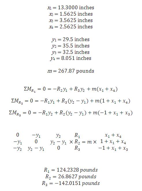
Assuming static equilibrium, the values of the lengths and weights and the equations of motion are as follows:
Using matrix algebra we are able to solve for the three reaction forces. The values are as anticipated and can be interpreted as follows: the reaction force at roller 1 is 124 lbs to the right, the reaction force at roller 2 is 27 lbs to the right, and the reaction force at roller 3 is 142 lbs to the left. While these values do not add to zero as they should in static equilibrium, there is only a minor discrepancy. This can be accredited to approximation of the weight and center of mass of the mower on the platform.
Prototype Documentation
Throughout the design process, we constructed three prototypes to physically analyze our design and improve upon it. These prototypes were essential to obtaining a high-quality functional final prototype and design.
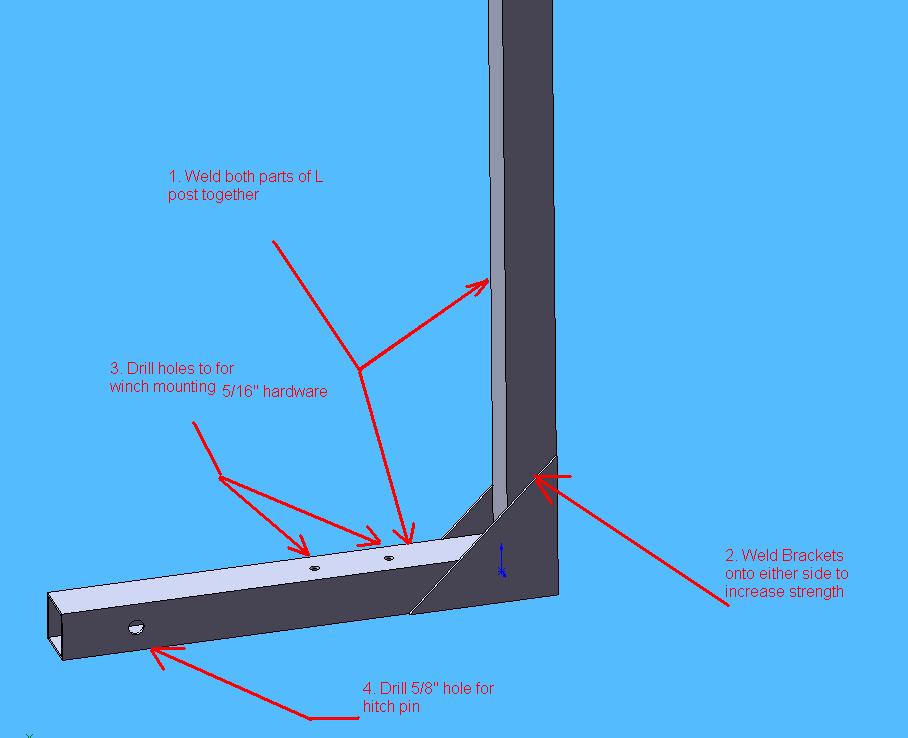
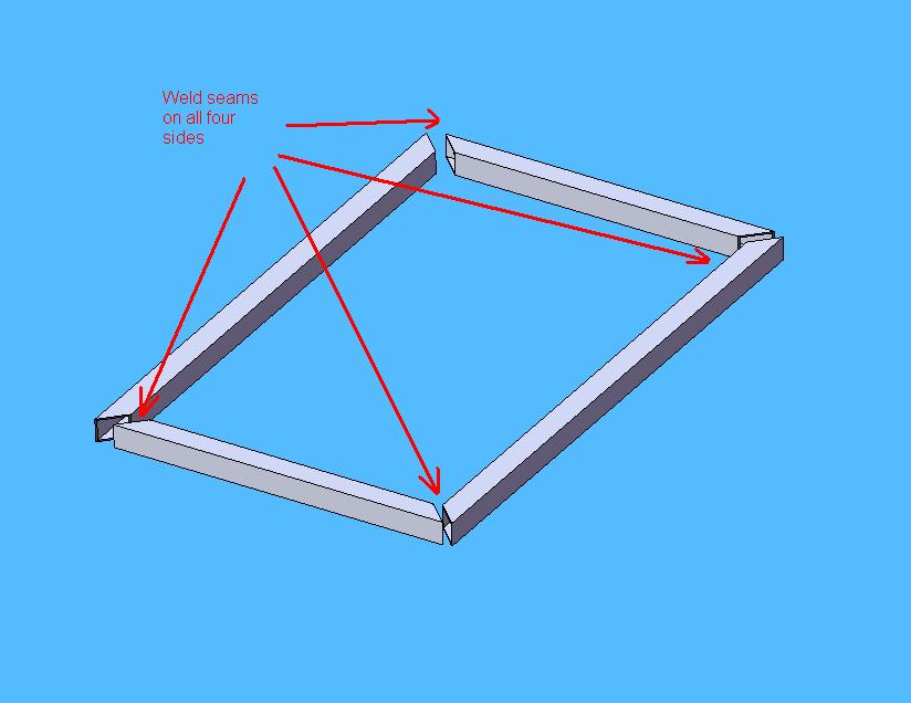
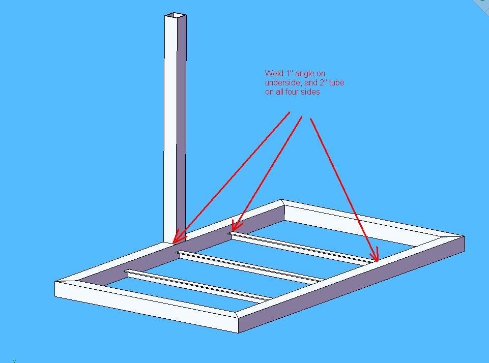
Prototype I The blueprint of our first prototype was surprisingly similar to that of our final prototype. It was constructed primarily out of wood, and was intended to demonstrate the lifting method of our product. The prototype consisted of a platform, pulley system, hand crank (to simulate a winch), and a clamping piece. We noticed with this prototype that it was quite difficult to actually lift the platform, which gave us ideas for improvement upon the pulley system and material choices.
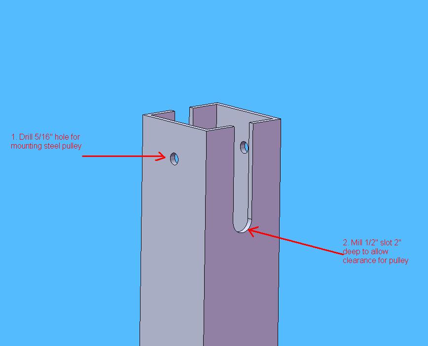
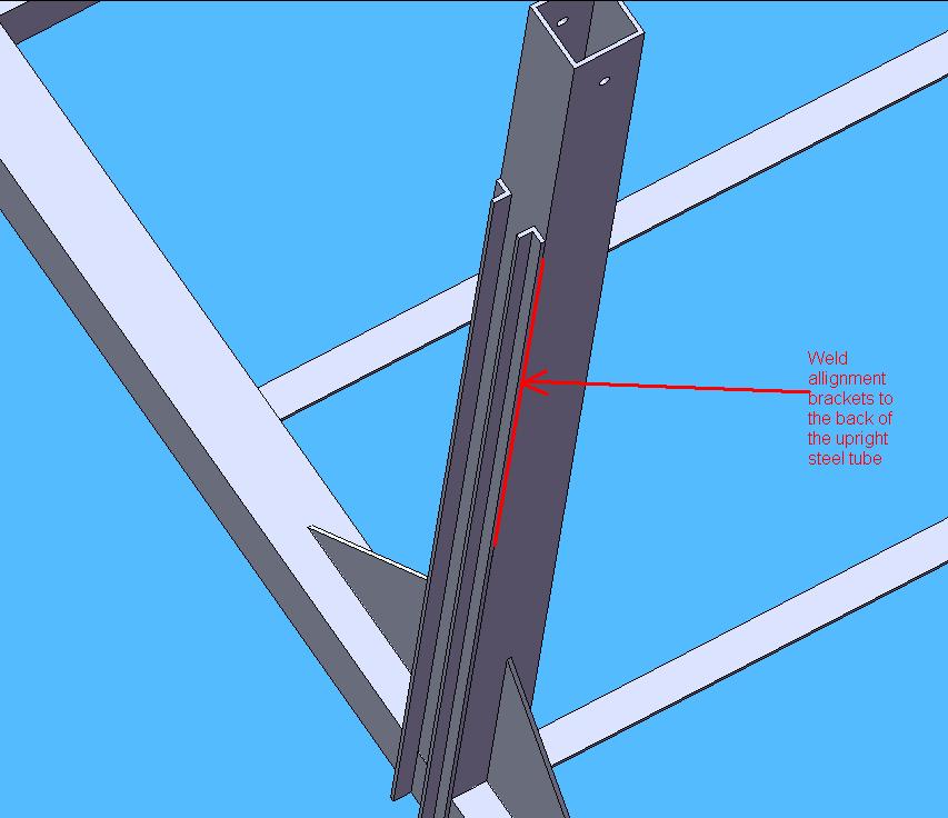
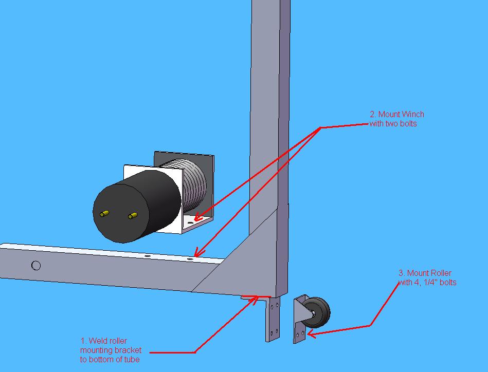
Prototype II Our second prototype was constructed using the base of Prototype I, but we incorporated the new pulley system that we had designed since our first prototype. This prototype was intended to demonstrate the ease of lifting with the application of this new pulley system. As opposed to having a pulley located on the winch-side of the device and lifting it from this side, we chose to place a pulley at the top of the device and lift the mower from the platform-side of the device. We also incorporated some new material choices, including the delrin rollers, which resulted in a smoother lifting of the platform.
