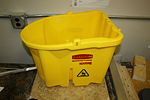
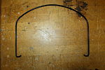
Mop wringer
From DDL Wiki
Contents |
Executive Summary
After in depth studies performed on both a mop-bucket wringing device and a self-wringing folding mop it is clear that significant improvements can be made to components of each device.
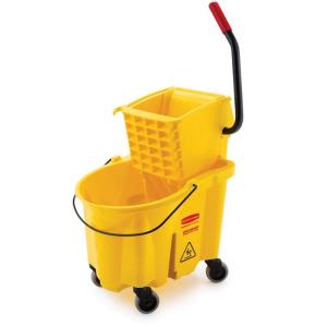
Following the usability study we realized that inefficient wringing out of the mop and sponge respectively were major problems. Additionally in the mop bucket, lots of force was required to pull the wringing plates together which created a moment about mop bucket that could lead to the entire thing tipping over and spilling water onto the floor.
Following the Design for Manufacture and Assembly we found that the devices were designed with limited number of different parts to simplify te assembly procedure. Additionally, the mop bucket could be broken down into sub-assemblies to help simply assembly. The most complex components of the device, the water bucket and two wringing plates were both injection molded while the more complex wheels and fasteners were all standardized throughout the device.
Performing a study of Failure Modes and Effects made it clear that parts involved in the wringing process had the highest RPNs, primarily the wringer plates in both devices. If this mechanism fails then the mop will no longer be usable.
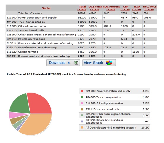
Design for Environment showed us that the producers of the mop bucket did a pretty good job in limiting greenhouse gas emissions with room for slight improvements in CO2 emissions in the power and generation sector.
Taking all of the analysis into consideration our team recommends the design of a novel mop wringing system to mitigate the usage, manufacturing and assembly and failure mode concerns mentioned throughout the report.
Stakeholder Analysis
In analyzing the two identified mops, five primary stockholders were identifies. Furthermore, the category of consumers can be broken down into private and public consumers, creating two subdivisions. Throughout the analysis, many of the stakeholders were found to hold similar interests and yet many also held various unique values.
Manufacturers
1) The cost to produce the product must be minimized/as low as possible
2) The product must be able to be mass produced in order to fill large orders
3) The product should not require extensive assembly time so that more products can be produced in a certain amount of time
4) Manufacturing this product cannot have a large negative impact on the environment
5) The product must be easy to store and package to maximize the quantity able to ship at one time
Investors
1) The cost to produce the product must be minimized/as low as possible
2) The product must employ a significant and effective innovation when compared to current designs so that the new design will be more desirable to the consumer
3) The product must be aesthetically pleasing and appeal to the consumers' interest
4) The market for this product must be large enough so that there is a reasonable possible profit margin
Retailers
1) The product must be of reasonable shape and size to optimize storage space in the storage facility as well as retail floor
2) There should be a general interface that can interact with various cleaning supplies, mop heads, etc. in needed
3) The wholesale cost should be low so that a profit can be made without marking the retail cost far above that of competitor products
4) The product must be aesthetically pleasing and appeal to the consumers' interest
5) The product must be effective at its task so that the store maintains its reputation of product selection
Cleaning Supply Companies
1) There should be a general interface that can interact with various cleaning supplies, mop heads, etc. if needed
2) The product should be manufactured from a material that is compatible with the various types of common cleaning solutions
Consumers
Private Consumers
1) The cost of the product must be low compared to competitor products
2) The product must be aesthetically pleasing and appeal to the consumers' interest
3) The product should require minimal effort to clean (i.e. have minimal hard-to-reach features)
4) The product should have a long life span and be durable in order to survive hits, knocks, falls, etc.
5) The product must be easily portable over both short and long distances
6) The mechanical design of the product must be simple and intuitive in order to avoid confusion and misuse
7) The weight of the product needs to be minimized so that all types of users are able to correctly use it
8) The product needs to be easily stored
Commercial Consumers
1) The cost of the product must be low compared to competitor products
2) The product should have a long life span and be durable in order to survive hits, knocks, falls, etc.
3) The weight of the product needs to be minimized so that all types of users are able to correctly use it
4) The weight of the product needs to be minimized so that all types of users are able to correctly use it
5) The product should require minimal effort to clean (i.e. have minimal hard-to-reach features)
6) The product must be quiet and not disturb the commercial atmosphere while in use
7) The product must be easily noticed and recognizable for both the user and others
Usage
Product Use Steps
| Mop and Bucket Combination | Self-Wringing Folding Mop | |||||
|---|---|---|---|---|---|---|
| Step # | Description | Image | Step # | Description | Image | |
| 1 | Make a mess | 1 | Make a mess | |||
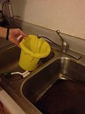
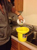
| 2 | Fill bucket with water | 2 | Obtain a bucket | |||
| 3 | Add recommended amount of cleaning solution | 3 | Fill bucket with water | |||
| 4 | Put mop in bucket | 4 | Add recommended amount of cleaning solution | |||
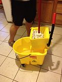
| 5 | Move mop to wringer | 5 | Put mop in bucket | |||
| 6 | Wring out mop | 6 | Slide wringer towards end of mop, over the bucket | |||
| 7 | Mop floor (i.e. move back and forth across desired dirty surface) | 7 | Mop floor (i.e. move back and forth across desired dirty surface) | |||
| 8 | Repeat steps 4-7 until desired cleanliness is achieved | N/A | 8 | Repeat steps 5-7 until desired cleanliness is achieved | N/A | |
| 9 | Empty bucket | 9 | Empty bucket | |||
| 10 | Repeat steps 2-3 as desired | N/A | 10 | Repeat steps 3-4 as desired | N/A |
Mechanism
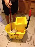
The primary mechanism in both of the above devices is the wringing system. The mechanism operates very differently in each device; however, both have their own advantages and disadvantages. In the mop bucket device the mop and wringer are separate from each other while in the folding mop the wringer is built into the device.
The mop bucket wringer utilizes two plastic plates that are pulled together via a handle pulled by the user. The folding mop wringer utilizes a sliding hand grip that forces two metal rollers over the sponge, causing it to fold in half.
User Studies
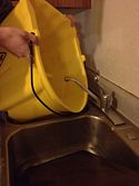
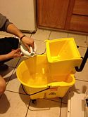
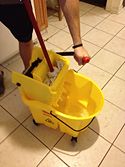
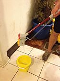
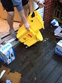
After analyzing the usage of each device within our group we discovered several pitfalls in each design. First, the wringing-system in the mop bucket design is very inefficient. It takes a lot of force from the user to wring water out of the mop and does not always squeeze evenly on the mop. Additionally, when applying the large amount of force on the wringer it can create a moment on the mop bucket and cause it to tip over, spilling the water on the floor. Other design flaws include wheels that allow the bucket to slide around when you are trying to wring out the mop and no easy way of emptying the water and cleaning solution from the bucket after use.
In the folding mop device there were also several design flaws that we decided could be improved upon. The primary mechanical component, the hand-wringing system, while very simple to use, is not very effective. It does not fully wring out the sponge on each use. Also, the sponge attachment on the end is very difficult to take off and replace, which limits the reusability of the device. Also, the mop is sold by itself without any water bucket included so the user must also purchase this as well.
Bill of Materials
Mop Bucket
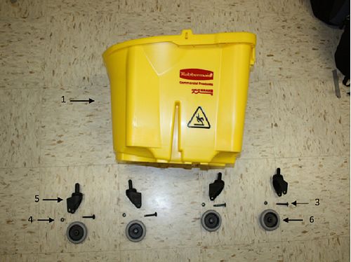
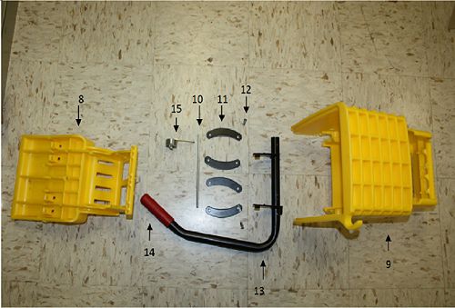
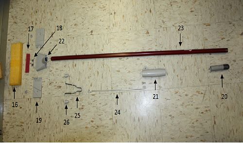
The mop bucket device was split up into two sub-assmeblies; the water bucket and the mop wringer. The folding mop was left as a single assembly. Exploded views of each of the assemblies are shown below with their relative bill of materials.
Mop Wringer
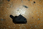
| Part # | Part Name | Quantity | Description | Material | Manufacturing Process | Weight (g) | Image |
|---|---|---|---|---|---|---|---|
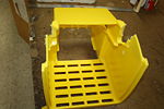
| 8 | Upper Wringer Plate | 1 | Translates toward the bottom wringer plate to compress the mop head and squeeze water into bucket | Plastic | Injection Molded | 781 | |
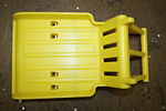
| 9 | Bottom Wringer Plate (Wringer Base) | 1 | Provides a rigid surface for the upper wringer plate to compress the mop head against | Plastic | Injection Molded | 1520 | |
| 10 | Linkage Stabilizing Pin | 1 | Creates a uniform starting point for linkages to push off from thereby stabilizing upper wringer plate when being compressed | Aluminum | Extruded, cut | 48 | |
| 11 | Upper Wringer Plate Linkage | 4 | Controls translation of upper wringer plate towards bottom wringer plate to compress mop head | Steel | Stamped | 69 | |
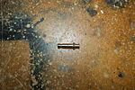
| 12 | Rivet | 2 | Secures wringer lever to linkages | Aluminum | Purchased | 4 | |
| 13 | Wringer Lever | 1 | Controls movement of upper wringer plate and therefore the compression of the mop head | Aluminum | Extruded, cut, bent (purchased) | 937 | |
| 14 | Lever Handle Cover | 1 | Provides friction surface and safety feature for operating lever | Rubber | Molding | 27.8 | |
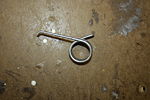
| 15 | Level Torsional Spring | 1 | Resists compression of upper wringer plate and returns it to its original, open position | Aluminum | Extruded, bent (purchased) | 4.4 |
Folding Mop
| Part # | Part Name | Quantity | Description | Material | Manufacturing Process | Weight (g) | Image |
|---|---|---|---|---|---|---|---|
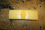
| 16 | Sponge | 1 | Soaks up water, cleans floor | Synthetic Sponge | Purchased, cut | 50 | |
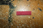
| 17 | Scrubbing Pad | 1 | Allows scrubbing for hard to clean messes | Plastic | Purchased, cut | <1 | |
| 18 | Folding Plates Spring | 1 | Returns two folding plates to linear position to mop floor | Aluminum | Extruded, cut, bent (purchased) | 4 | |
| 19 | Folding Sponge Plate | 2 | Folds towards opposite plate to squeeze excess water out of sponge | Plastic | Injection Molded | 23 | |
| 20 | Mop End Cover | 1 | Allows for the mop to be hung on a hook/nail, provides aesthetic design | Plastic | Injection Molded | 18 | |
| 21 | Plate Folding Handle | 1 | Slides along mop rod to fold bottom plates together and squeeze out excess water | Plastic | Injection Molded | 38 | |
| 22 | Sponge Mount | 1 | Attaches sponge to mop rod | Plastic | Injection Molded | 47 | |
| 23 | Mop Rod | 1 | Controls movement of the mop head | Aluminum | Extruded, cut | 186 | |
| 24 | Folding Rod | 1 | Translated force from folding handle to folding plate spring and plates | Aluminum | Extruded, cut, bent | 35 | |
| 25 | Folding Plate Compressor | 1 | Pushes the folding plates towards each other to squeeze out excess water | Aluminum | Extruded, cut, bent | 51 | |
| 26 | Folding Plate Compressor Roller | 2 | Rolls along folding plates and pushes them together as the folding handle is pushed toward the mop head | Plastic | Injection Molded | 2 |
Design for Manufacturing Analysis
Through dissecting the competitors mop, much was learned about design decisions regarding manufacture and assembly. It was quickly realized that the wringer and bucket are comprised of relatively few parts. Also, the use of fasteners was kept to a minimum and the wringing mechanism is dynamically simple. Limiting both parts and fasteners play an overarching and significant role in keeping cost to a minimum and ease of manufacturing to a maximum. Additionally, it was found that the competitor took into account economies of scale by standardizing components, namely the castor wheels and the wringing mechanism linkages. Each ringer and bucket contain four castor wheels and four linkages. Therefore, through standardizing these parts, the advantages of mass production can be maximized by limiting the need to change tooling in manufacturing. The injection molded parts, on the other hand, seem not to be as highly standardized and are, in fact, the most complex pieces of the assembly. This makes sense that the machined/tooled parts are kept simple while the molded parts are complex and innovative. If the molds are going to be created anyway, additional component complexity does not add to manufacturing complexity or effort. It should also be noted that the injection molding allows for the bucket and wringer to be colored yellow without painting, which would add another step in the manufacturing process. The final part of the design that influences manufacturing is the precision of the components. Minimal precision and secondary finishing is required because tolerances are rather large in the wringer and bucket. Wringing out a mop requires low precision and this greatly reduces manufacturing effort and cost.
Looking at the competitor’s product from an assembly perspective illuminates some similar and different design decisions. One similarity to design for manufacture was the use of relatively few parts. This proved to be important because limiting the overall parts reduces assembly time and effort. One aspect of the design for assembly that could potentially be improved is the shape of the linkages in the wringer mechanism. Although they are unilaterally symmetric, making them bilaterally symmetric could reduce assembly time and mistakes. Another aspect of the design for assembly was maximizing assembly compliance. The snap together parts included molded chamfers which allowed the pieces to join together despite relatively large assembly variance. The final aspect of the design for assembly that was analyzed was the assembly path, in particular the wringer lever. It appears that it had to be inserted into the wringer first, then linkages were welded onto it in the appropriate places. An improvement would be to have the linkages attached to the lever prior to the lever being inserted into the wringer. It would seem that welding the linkages onto only the lever would be less cumbersome and more cost effective than welding them onto the lever once it has already been inserted into the wringer.
Overall, after dissecting the competitors mop, one can see that manufacturing and assembly were undoubtedly taken into account in the design. With this being said, however, there is still room to improve in both regards.
Failure Mode and Effect Analysis
The analysis of failure modes and the effects it has on the consumer or the product must be taken into consideration when redesigning a product. It is important that the product be designed such that it is safe and reliable for the consumer. The evaluation of the product using FMEA allows for us to address the possible effects of failure early on in the design stage.
Numerical Ratings:
S: Severity of Failure (1: Effect not noticed by consumer - 10: Hazardous, failure occurs without warning; life threatening)
O: Occurrence of Failure (1: Extremely unlikely - 10: Extremely high occurrence)
D: Detection of Failure (1: Certain to detect - 10: No chance of detection; no inspection)
RPN: Risk Priority Number = Severity (S) x Occurrence (O) x Detection (D)
After evaluating the product, the parts that were found to have the highest RPNs were those associated with the wringing process and the wheel mount pin. The wringer plates and accompanying parts had high RPNs because if the wringer on the bucket fails it becomes ineffective and the system as a whole will prove to be useless. The specific parts associated with the wringer that stood out during the analysis were the wringer plate linkage, the linkage stabilizing pin and the rivet. These three components hold the wringing system in place. If any one of the aforementioned components were to fail the design would fail completely. Similar results were calculated for the wringing mechanism on the mop rod. If the parts associated with the linkage mechanism fail then the mop will no longer be usable. The wheel mount pin had a high RPN because like the link and pin system, if the part were to fail then many other parts would also fail. During the redesign process most of the focus will be on improving the bucket wringing system, the wringing system on the mop and the wheels on the bucket.
| Part # | Item | Function | Failure Mode | Effects of Failure | S | Causes of Failure | O | Design Controls | D | RPN | Recommended Action |
|---|---|---|---|---|---|---|---|---|---|---|---|
| 1 | Bucket | Holds water and cleaning solution, collects water drained from mop | Breaks/cracks | Can no longer hold water; unusable bucket | 2 | Dropping/hitting | 3 | Durable/hitting | 2 | 12 | Replace bucket or seal crack |
| 2 | Bucket handle | Allows user to pick up bucket (e.g. move up/down stairs, into car) | Detaches from bucket | Can no longer transport bucket | 5 | General wear, Lifting/Pulling with extreme force | 4 | Permanently attach handle to bucket, design a more durable connection | 2 | 40 | None |
| 3 | Upper Wringer Plate | Translates towards the bottom wringer plate to compress the mop head and squeeze water into bucket | Breaks/cracks | Can no longer wring mop | 5 | Overuse, dropping/hitting, improper lever use | 4 | Durable plastic | 2 | 40 | Replace bucket or seal crack |
| 4 | Bottom wringer plate (wringer base) | Provides a rigid surface for the upper wringer plate to compress the mop head against | Breaks/cracks | Can no longer wring mop | 5 | Overuse, dropping/hitting | 4 | Durable plastic | 2 | 40 | Replace bucket or seal crack |
| 5 | Linkage Stabilizing Pin | Creates a uniform starting point for linkages to push off from, thereby stabilizing upper wringer plate when being compressed | Loosening | Can no longer wring mop; wringer falls apart while in use | 5 | General wear, user tampering | 6 | Improve on the connection of the pin to the bucket, perform dynamic load testing on pin | 2 | 60 | Replace pin |
| 6 | Upper wringer plate linkage | Controls translation of upper wringer plate towards bottom wringer plate to compress mop head | Loosening | Can no longer wring mop; wringer falls apart while in use | 5 | General wear, user tampering | 6 | Improve on the connection of the linkages to pin, Perform fatigue testing on the connection | 2 | 60 | Replace bucket |
| 7 | Rivet | Secures wringer lever to linkages | Loosening | Can no longer wring mop; wringer falls apart while in use | 5 | General wear; user tampering | 6 | Improve on the connection of the pin to the lever, perform dynamic load testing on the pin | 2 | 60 | Replace rivet |
| 8 | Wringer lever | Controls movement of upper wringer plate and therefore the compression of the mop head | Detaches from wringer | Can no longer wring mop with lever; wringer falls apart during use | 5 | General wear, Pushing/Pulling with extreme force | 4 | Permanently attach lever to bucket, design a more durable connection | 2 | 40 | None |
| 9 | Lever torsional Spring | Resists compression of upper wringer plate and returns it to its original, open position | Loosens, detaches | Can no longer wring mop with lever; wringer falls apart while in use | 7 | Overuse - general wear, user tampering | 3 | Secure to lever, Perform fatigue testing | 2 | 42 | Replace spring |
| 10 | Wheel bolt | Secures wheel inside wheel mount | Loosening | Bucket falls of fails while in use | 2 | General wear, user tampering | 4 | Use screw that requires specialized tool to unscrew | 1 | 8 | Screw the bolt back on |
| 11 | Wheel nut | Secures wheel inside wheel mount | Wheel falling off of the mount | Bucket falls or fails while in use | 2 | General wear, user tampering | 2 | Permanently attach wheel to mount | 1 | 4 | Replace nut |
| 12 | Wheel mount | Provides interface to connect wheels to bottom of bucket | Breaks/cracks | Wheels fall off of bucket, bucket fails | 2 | General wear, user tampering, dropping/hitting against rigid object | 3 | Permanently attach wheel to mount | 1 | 4 | Replace mount, replace bucket |
| 13 | Wheel mount pin | Connects the bucket interface to wheel bolt lock | Loosening | Wheels fall off bucket, bucket fails | 5 | General wear, user tampering | 6 | Improve on the connection of the pin to the mount, Perform dynamic load testing | 2 | 60 | Replace pin |
| 14 | Sponge | Soaks up water, cleans floor | Tear, wear out | Can no longer soak up water | 5 | General wear, user tampering | 6 | None | 2 | 60 | Replace sponge |
| 15 | Scrubbing pad | Allows scrubbing for hard-to-clean messes | Tear, wear out | Can no longer scrub/clean floor | 5 | General wear, user tampering | 6 | None | 2 | 60 | Replace scrubbing pad |
| 16 | Folding plates spring | Returns two folding plates to linear position to mop floor | Loosens, detaches | Can no longer wring out sponge | 5 | Overuse - general wear, user tampering | 3 | Secure to lever | 2 | 30 | Replace spring |
| 17 | Folding sponge plate | Folds towards opposite plate to squeeze excess water out of sponge | Breaks/cracks | Can no longer wring mop | 5 | Overuse, dropping/hitting | 4 | Make out of durable plastic | 2 | 40 | Replace mop |
| 18 | Plate folding handle | Slides along mop rod to fold bottom plates together and squeeze out excess water | Detaches from mop | Can no longer wring sponge with lever, wringer falls apart while in use | 5 | Overuse - general wear, breaking/hitting against rigid object | 4 | Permanently attach lever to bucket, make a more durable connection | 2 | 40 | None |
| 19 | Sponge mount | Attache sponge to mop rod | Loosens, breaks/cracks | Sponge can no longer be connected to mop rod, no longer have usage mop | 5 | Breaking/hitting against rigid object | 4 | Make out of durable plastic | 4 | 80 | Replace mop |
| 20 | Mop rod | Controls movement of the mop head | Breaks/cracks | No longer have a usable mop | 5 | Breaking/hitting against rigid object | 2 | None | 2 | 20 | Replace mop rod |
| 21 | Folding handle pin | Secures handle to the folding rod | Loosening | Can no longer wring sponge, wringer falls apart while in use | 5 | General wear, user tampering | 6 | Improve on the connection of the pin to the handle, Perform dynamic load testing | 2 | 60 | Replace pin |
| 22 | Folding rod | Translated force from folding handle to folding plate spring and plates | Detaches from mop | Can no longer wring sponge; wringer falls apart while in use | 5 | Overuse - general wear | 4 | None | 2 | 40 | None |
| 23 | Folding plate compressor | Pushes the folding plates towards each other to squeeze out excess water | Breaks, detaches | Can no longer compress the plates | 5 | Overuse - general wear | 4 | None | 2 | 40 | None |
| 24 | Folding plate compressor roller | Rolls along plates and pushes them together as the folding handle is pushed toward the mop head | Breaks, detaches | Can no longer compress the plates | 5 | Overuse - general wear, falling/breaking | 4 | Design a new way to compress the plates besides the rolling system | 2 | 40 | None |
Design for the Environment
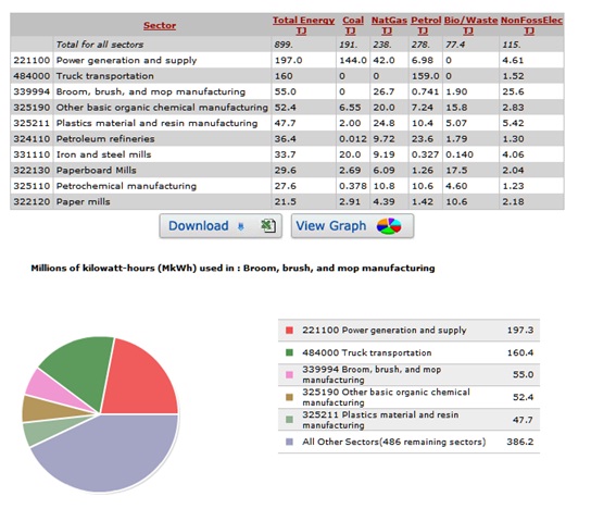
Design for Environment (DFE) is very important because of its ability to shape the design of a product before it is even manufactured. In order to assess the environmental impact of our product we used a tool known as Economic Input-Output Life Cycle Assessment (EIO-LCA). This tool estimates the materials and energy resources required for, and the environmental emissions resulting from, activities in the economy. We will use this tool specifically to find the yearly greenhouse gas emissions, economic impact, and the energy use of the product during the entire product’s life cycle. It is important to note that the product has no major impact on any sector while in the use stage. Also depending on the mode of disposal, there exists the potential for the product to be recycled which will have little to no impact on any sector while the product is at the end of its lifecycle. As a result, we will neglect to conduct an EIO-LCA analysis for the use and end stages.
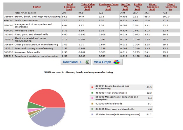
The charts above show that competitors did a good job at following guidelines which resulted in relatively good greenhouse gas emission numbers although there was room for improvement in the power and generation and the transportation sectors. These two sectors accounted for almost half of the CO2 emissions during the lifecycle of the product making them the major sources of CO2 in the products lifecycle as shown in figure 4. This leads us to believe that if a tax on CO2 were to be passed, there would be no large economic impact resulting from it. If any impact were to be felt, it would most likely occur in the manufacturing of the product as shown in figure 5.
Group Dynamic
Team lead: Brad Edelman
DFMA lead: Kyle Young
FMEA lead: Gabrielle Page
DFE lead: Danny Benvegnu
Summary and Editing lead: Bryan Good
Overall the team worked extremely well together. Sections of the report were divided up based on each individual team member's skills and rough drafts of each section were completed well in advance of the final deadline. The entire team then met together to help finalize each section and begin uploading the sections onto the Wiki page.
