Motorcycle throttle lock
From DDL Wiki
Contents |
Executive Summary
This is the executive summary.
Major Stakeholders and Product Needs
User
- easy to use
- safe
- easy to disengage
- durable
- attractive
- stays engaged over long distances and through vibrations
- intuitive to use
Installer
- easy to install and adjust for many different motorcycles
Retailer
- cheap
- attractive
- compact
Other motorists
- safe
- easy to disengage
Passenger
- safe
- reliable
- intuitive to use
Law enforcement
- Can failure lead to malfunction or an accident
Product Use
Type 1 (cruiser)
Operation
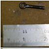
- The banjo bolt must be adjusted prior to use so that when the throttle lock is disengaged the throttle does not rub on the rubber ring, and when the lock is engaged the throttle sticks but can still be manually turned
To Engage
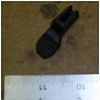
- While holding the throttle with the fingers and palm at the desired opening, press the thumb lever down into the engaged position. (The friction is such that the rider may still open and close the throttle. The throttle simply has a slight rotational stiffness.)
To Disengage
- while holding the throttle with the fingers and palm, press the oposite side of the thumb lever with the back of the thumb to place the throttle lock in the disengaged position.
Maintenance
- Remove periodically and check for rust or dirt build up. Clean pieces with brush and mild soap. Replacement parts may be required over time.
Type 2 (sport bike)
Operation
- The friction nut has a left hand thread. In readiness for engagement, it must be adjusted so that it makes light contact with the plastic thrust washer.
To Engage
- While rolling on the throttle, the friction nut can be gripped between the small finger and palm of the hand. This action tightens the nut and provides sufficient friction to set the throttle to the desired opening. (The friction is such that the rider may still open and close the throttle. The throttle simply has a slight rotational stiffness.)
To Disengage
- While rolling off the throttle, grip friction nut between small finger and palm of the hand. VERY IMPORTANT!! The throttle should open and snap close freely when correctly disengaged.
- Note: The Grub Screw is set to provide the necessary resistance on thread of friction nut. This may be adjusted periodically to take up wear. Use 2mm allen key.
Maintenance
- Remove kit annually. Unscrew friction nut and brush clean threads with mild soap. Apply petroleum jelly to threads and assemble. Adjust grub screw to desired operating resistance. Use the 2mm key.
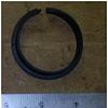
(O-Ring cushion: 19.6mm I.D. x 2.4mm section - if replacement is required)
Reference: KAOKO Cruise Control Kits User and Safety manual that came with the product.
Dissection procedure and exploded assembly
Dis-assembly procedure for Type 1 Throttle Lock
- Removing clamp
- take off clamp screw nut
- remove washer and spring
- separate main assembly into two sub-assemblies
- throttle lock sub-assembly
- handle bar clamp sub-assembly
- Dis-assemble locking mechanism
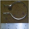
- remove metal clamp
- remove clamp screws (3)
- Dis-assemble thumb lever
- remove axial screw
- Dis-assemble handle bar clamp
- remove screws (2)
- Analyze auxiliary parts
- rubber clamps
- wide throttle adapter with screw
- Cut out main body clamp set threads
- cut with hack saw
Dis-assembly procedure for Type 2 Throttle Lock
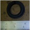
- Remove plastic thrust washer
- Unscrew left hand friction nut
- Remove O-Ring cushion with needle nose pliers
Mechanical Function
Type 1 (cruiser)
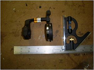
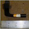
This product is used to lock the throttle on a motorcycle. The usual way of riding a motorcycle requires the rider to hold the throttle on at all times to accelerate. This can lead to fatigue on long trips. This product uses a metal clamp with a plastic washer to hold the throttle in the on position while letting the rider relax his hand. There is a small spring and plastic switch for functionality and when the switch is turned off, it quickly allows the throttle to go to zero.
Type 2 (sport bike)
This product serves the same purpose as the cruiser type throttle lock. This products different in how it accomplishes the task. The sport bike throttle lock is located on the outside of the throttle (directly to the right of one's right hand). It takes the place of the right hand end weight that sport bikes have. In order to "lock" the throttle the rider must turn the large nut on the throttle lock in the same direction as the accelerator. This will cause the nut to press against a washer which then presses against the motorcycle's throttle. The added friction from the washer being tightened by the left hand nut causes the throttle to be held in place. Unlike the cruiser style lock, this product does not have a "quick" release feature like some of its competing products. The user must manually tighten and loosen the throttle lock. It is possible to move the throttle while the throttle lock is engaged so long as it has not been over tighten. Although there is no quick release, this product is a very simple and effective cruise control for sport motorcycles.
Bill of Materials and Properties
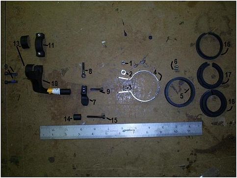
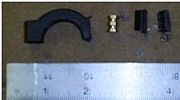
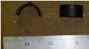
When disassembling the product, we discovered that it has 19 unique parts, and cataloged their function, material, and manufacturing processes in the following BOM.
DFMA
DESIGN FOR ASSEMBLY:
- Minimization of Part Count
- While there were some extra parts included with the product, they were included for the purpose of increasing the flexibility of the design by allowing its fitment to multiple types of motorcycles
- Minimization of Assembly Surfaces
- The throttle lock is of a simple enough design that to decrease the number of surfaces would drastically increase the complexity of the product or reduce its effectiveness
- Use of Sub-Assemblies to ease assembly
- The ability to break the product down into a few sub-assemblies makes its assembly much clearer and allows it to be done in stages
- Idiot-Proofing of Product
- Because of the simplicity of the design, there is little if any opportunity for the consumer to assemble it incorrectly and in the event that they do, it would be either immediately apparent and not damage the product, or it would have no effect on the usability anyway
- Minimization of Fasteners
- This is done very well, any reduction in the number of fasteners would vastly increase the complexity.
- Minimization of Handling
- This is not an area that is done exceedingly well, but the difficulty comes mainly from the fact that it is a multi-fit product and as with all of the other areas in which it is lacking, any strides that could be made in this area would greatly increase the complexity of manufacture and thereby the cost as well.
- Minimize Assembly Direction
- This is done as well as is possible and no way of furthering it could be discerned.
- Provide Unobstructed Access
- Because of the multi-fit abilities, some situations may arise where there need to be minor modifications made to the mounting position of parts on the bike. In our particular case, the brake master cylinder and cup-holder needed to be moved over ~.5".
- Maximization of Assembly Compliance
- Threaded sections are counterbored before thread engagement aiding in not cross-threading of fasteners.
- Additions to Product Aiding Assembly
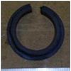
- There were some parts allowing its multi-fit ability that become extras depending on the application, such as the rubber rings (parts 16-18)where only one is used, but there are multiple options for which one will be used.
DESIGN FOR MANUFACTURE:
FMEA
FMEA: Motorcycle Throttle Lock
The **** scale was used from the book. Most of the possible failures of the throttle lock result in the jamming of the throttle lock or the breaking of a key mechanism part in the disengagement or engagement of the throttle lock. This could cause serious problems and dangers to a user if such a failure occurred while user was driving his or her motorcycle. A driver can over ride the throttle lock by manually using the motorcycle throttle, but quick reactions and appropriate actions would need to be taken for a driver to avoid a crash and potentially deadly injuries. For example, if the the clamp of the throttle was over-tightened in the installation process this could make it impossible or very difficult to engage or disengage the the throttle lock. Forceful turning of the throttle lock itself may be necessary to use the throttle lock. This failure is the result of misuse or improper installation by the user, but the use of a shoulder bolt in the clamp could potentially prevent this from being possible. This is the least likely and least dangerous of the potential failures which can be seen by its low RPN number. Rust in the clamp rings is another potential way for the throttle lock to become jammed or harder to use. With the current metal being used, it is only a matter of time and extended use before rust occurs and potentially leads to failure which can be seen by the second highest RPN value. Finally and most dangerously, the thumb push which is used to disengage or engage the throttle lock could break. This is the most dangerous failure because it could occur suddenly and surprisingly while a user is driving his or her motorcycle. If the throttle push breaks then this would could lead to a catastrophic failure of the throttle lock. Manual use of the motorcycle would be needed if this occurred. Better material than plastic could be used to lessen the chance of this or a replacement thumb push could be sold so that users could replaced an old and failing thumb push.
| Item & Function | Failure Mode | Effects of Failure | S | Causes of Failure | O | Design Controls | D | RPN | Recommended Actions |
|---|---|---|---|---|---|---|---|---|---|
| Clamp 1) used to attach throttle lock to motorcycle handle and throttle. | Clamp is over tightened. (screw) | It makes it difficult or impossible to disengage throttle lock. | 8 | The failure is caused by an over-tightening of the clamping screw during installation. | 4 | Different bolt designs such as a shoulder bolt could prevent this from being possible. | 2 | 8x4x2=64 | 1) Correct installation or a better installation document which lists this as a potentially dangerous action.
2) The use of a shoulder bolt could prevent this from being possible, and therefore solves the problem. |
| Clamp Ring
1) used to allow rotation between motorcycle throttle and throttle lock. | Clamp ring rusts over time. | The rust increases the friction and locking of the throttle. | 6 | Accumulation of rust over time due to elements encountered while driving or during storage. | 8 | Better materials can be used to prevent rust from occurring. | 5 | 6x8x5=240 | A greater focus and testing of materials and eventual material selection can be taken to find a material with less potential to rust. |
| Thumb Push
1) Mechanism used to change throttle lock from lock to unlocked position or vise versa. | The breaking of the thumb push. | This would make it impossible to disengage clamp. | 7 | Wear and tear from weather, general use, and decomposition of material over time. | 7 | Better material selection could extend life time of the thumb push. | 5 | 7x7x5=245 | Better material selection could prevent this. Or a replacement part could be offered for users to replace their old thumb push after extended use. |
DFE
Team Members and Roles
- Brandon VanTassel - Team Leader
- Matthew Doncheski - DFMA Lead
- Randall Oakes - FMEA Lead
- Nicholas Petrillo - DFE Lead
