Paintball marker
From DDL Wiki
(→Design for Environment - DFE) |
(→'''Executive Summary''') |
||
| Line 1: | Line 1: | ||
=='''Executive Summary'''== | =='''Executive Summary'''== | ||
| - | By way of our analysis of | + | By way of our analysis of this paintball marker, the Spider Shutter, we have identified several areas for design improvement. The following page will cover, in depth, our analysis of the product itself. In researching the conventional, and less conventional, uses of this particular marker, we have identified the primary objectives that this particular model would be expected to fulfill. The primary use of the Spyder Shutter is for entertainment purposes in conventional paintball games. By reviewing the customer needs and stake holders we have identified several areas for possible improvement on the Spyder Shutter. Customer needs are the main concern for the stake holders because if all of them are met, it will ultimately be beneficial to all of the stake holders involved. Some of the needs include: easy assembly, reliability and accuracy. |
| - | + | ||
=='''Conventional and Unconventional Purposes'''== | =='''Conventional and Unconventional Purposes'''== | ||
Revision as of 22:04, 11 February 2007
Executive Summary
By way of our analysis of this paintball marker, the Spider Shutter, we have identified several areas for design improvement. The following page will cover, in depth, our analysis of the product itself. In researching the conventional, and less conventional, uses of this particular marker, we have identified the primary objectives that this particular model would be expected to fulfill. The primary use of the Spyder Shutter is for entertainment purposes in conventional paintball games. By reviewing the customer needs and stake holders we have identified several areas for possible improvement on the Spyder Shutter. Customer needs are the main concern for the stake holders because if all of them are met, it will ultimately be beneficial to all of the stake holders involved. Some of the needs include: easy assembly, reliability and accuracy.
Conventional and Unconventional Purposes
Below is a list of different uses customers have been know to use a paintball marker for. The most conventional use for it is paintball games for entertainment purposes.
- Marking Cattle
- Marking Trees
- Non-Lethal Live Action War Simulation Training
- Paintball Games
- Fun and Entertainment
- Law Enforcement
Some of these uses of a paintball marker seem far fetched and a little absurd, however they have been used for all of these purposes.
Customer Needs and Product Requirements
Paintball markers were initially designed for marking trees, trails and cattle. Today, the marker is predominantly used in the sport of paintball and as a result the product has needed to be altered so as to better fulfill the needs of this new scope of customers. A paintball player needs his/her marker to be sturdy and to be able to endure a significant amount of physical damage. The marker also needs to be easy to assemble/diassemble as well as easy for the user to clean, maintain and store away. Due to the fact that the user will be running around with the product, it needs to be lightweight and easy to hold/carry.
In terms of product requirements, the marker needs to be designed in such a manner that the paintball is fired out of the barrel at velocity of around 300 ft/s (91m/s). This is due to the fact that at this velocity a paintball will not be traveling fast enough to severely hurt an opposing player (players would only suffer mild bruising when hit by a paintball) but it is still traveling fast enough so that it breaks upon impact. The marker needs to be made of lightweight materials so that the users can easily carry it and run with it. The marker also needs to be designed in such a manner that users can upgrade their markers conveniently. This includes upgrades such as changing the barrel, the trigger frame, the hopper (holds paintballs in marker), the gas tank and so forth. The marker's trigger frame needs to be constructed in such a manner that an average person's hand can hold the marker comfortably. Another factor which needs to be taken into consideration is that paintballs do not explode in the barrel itself. The marker must also be safe for the user to operate.
Summarized:
Customer Needs and Product Requirements
| Customer Needs | Product Requirements |
|---|---|
| Sturdy | Safety |
| Easy Assembly | Paintball Speed |
| Easy to Clean | |
| Lightweight and Comfort | Lightweight and Comfort |
| Economical | Upgrade Options |
Inputs and Outputs
Below is a short list of all the inputs and outputs needed and produced to fire one paintball from the paintball marker. Each item is labeled for whether it is an input or an output.
- Pressurized CO2 (Input)
- Force of Pulling Trigger (Input)
- Paintballs (Input)
- Oil (Input)
- Paintball at High Velocity (Output)
- Expanded, Non-Pressurized CO2 (Output)
- Small amounts of excess oil (Output)
There are several inputs needed to fire one paintball from the marker. The most important of which is the pressurized CO2.
Stake Holders
There are several stake holders for paintball markers. These are the most common stake holders who the product affects the closest.
- Production Companies
- Paintball Gun Manufacturers
- Professional Paintball Players
- Recreational Paintball Players
- Retail Stores
- Paintball Arenas
The greatest stake holders are the paintball gun manufacturers. If their design is inferior in any way, people will not buy it and the company will loose money until they address the issue. Also, the paintball gun manufacturers are continually looking for possible improvements to gain an edge on the market.
Operation Procedures
Below is a complete list of steps required to fire off one paintball. The steps must be done in order for the marker to function properly.
1)Apply oil to CO2 tank connector
2)Cock bolt
3)Connect tank
4)Open CO2 valve
5)Dry fire 10-15 times
6)Attach barrel
7)Attach hopper elbow
8)Attach hopper
9)Fill hopper with paintballs
10)Disengage power feed
11)Aim gun at target
12)Pull trigger
13)Repeat as neccessary
The setup is the most intensive part of firing the marker. Connecting the tank and applying the oil is very important before firing the marker.
Specific User Considerations
There are some user considerations that need to be addressed while designing a paintball marker. Some of these considerations are listed below and can be improved upon.
- Fatigue or weak arms can't lift gun steadily
- Extreme low temperatures
- Too rapid a rate of fire
- Assembly difficult for disabled users (lost arm, or finger)
- Bad vision
- Clogged Barrel or Debris in system
Debris in the system and the problems firing in low temperatures are possible considerations for design improvements.
Possible Areas of Improvement
Some areas where design improments can be made have been listed below. Many of these areas can be easily addressed, such as the trigger pull distance and gas efficiency.
- Shooting accuracy
- Shooting range and distance
- Gas efficiency
- Weight and size of marker
- Trigger pull distance
- Multiple projectile firing
- Reduction in number of components
- Ease of disassembly for cleaning and service
We have decided to address the area of multiple projectile firing.
Functional Operation
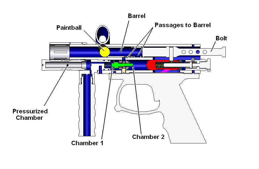
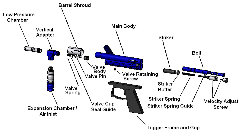
The following image is a section view of the paintball marker with the bolt in the cocked position and ready to fire. The description below describes the firing procedure and how each component is involved in propelling the paintball and re-cocking the gun for semi-automatic style firing. For a more detailed description and photo of each individual part, see the components list and exploded view below.
In order to fire the gun, you must first cock the bolt. This is done by pulling the bolt to the right until the striker (shown in red) engages with the trigger (shown in pink). When the trigger is pulled, the striker/bolt assembly is released and pushed to the left by the striker spring. While the bolt is moving, it pushes the awaiting paintball forward and prevents additional balls from entering the barrel. The striker then hits the valve pin (shown in green) and opens a passage from chamber 1 to chamber 2. At this point, the passages to the barrel are both lined up and the pressurized air can flow into the barrel and propel the ball forward. The pressurized air also flows through the valve body (shown in dark gray) back into chamber 2, which propels the bolt/striker back to the right and re-cocks the gun for another firing.
Components
| Part # | Part Name | Sub-Assemblies | Qty. | Function | Material | Manufacturing Process | Image |
|---|---|---|---|---|---|---|---|
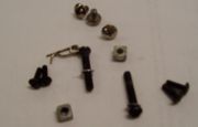
| 000 | Misc. Parts: Screws, nuts, pins, washers, o-rings | ALL | n/a | 1. Used for holding assemblies and parts in place 2. O-rings used for airseals 3. Lubricant used for wear protection and fluidity | Rubber/Silicon o-rings, steel screws, nuts, and other parts | Milled nut fittings for grip, purchased various other parts | |
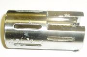
| 01 | Barrel | n/a | 1 | 1. Direct ball after exiting marker 2. Cause pressure gradient decreasing paintball deformation 3. Unscrews for easy cleaning | Anodized Aluminum | Turned on Lathe, Drilled out porting, Milled for aesthetics | |
| 02 | Barrel Shroud | n/a | 1 | 1. Aesthetics 2. Shields barrel/body connection area | Plated Aluminum | Turned on Lathe and Milled | |
| 03 | Sight Rail with Beaver Tail | n/a | 1 | 1. Provides a reference for aiming in a straight line 2. Protects user from moving bolt 3. Aesthetics 4. Shields Bolt | Anodized Aluminum | Extruded and Milled to final shape | |
| 04 | Main Body | n/a | 1 | 1. Houses bot, striker, and valve sub-assemblies 2. Provides adapters for barrel, hopper, grip frame, ball detent, sight rail, and air system 3. Window to view movement of bolt 4. Color and milling for aesthetics | Anodized Aluminum | Aluminum Extrusion, Milling and Drilled Holes, Welded on Powerfeed, Reamed inner bores | |
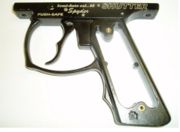
| 05 | Trigger Frame & Grip | Trigger Frame & Grip | 1 | 1. Attaches directly to main body 2. Double trigger for increased fire rate 3. Trigger guard to prevent accidental trigger pull 4. Grip provides stability for holding marker 5. Internals control bolt release 6. Holds attachment for drop forward and grip covers | Aluminum Alloy frame and trigger, Steel pins and levers, wire springs | Diecast frame and trigger with finish drilling and machining, milled levers, ground pins, press fit pins for assembly | |
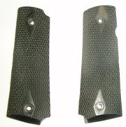
| 06 | .45 Grip Covers | Trigger Frame & Grip | 2 | 1. Attach to grip frame 2. Provide a rough grip 3. Hold drop froward nuts in place | Rubber | Injection Molded rubber | |
| 07 | Mini Drop Forward | Trigger Frame & Grip and Tank Adapter | 1 | 1. Attaches the tank adapter to the grip frame 2. Centers weight by moving tank forward 3. Milled for aesthetics and decreased weight 4. Lowers tank on marker | Anodized Aluminum | Milled and Polished, Drilled Holes | |
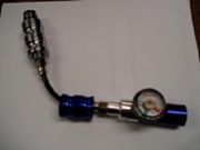
| 08 | Regulator/Expansion Chamber Assembly | Tank Adapter | 1 | 1. Transports air from tank to vertical adapter 2. Expansion chamber allows liquid CO2 to change to gas 3. Regulator controls flow from tank 4. Expansion chamber provides a front grip | Anodized Aluminum, Steel Fittings, Plastic Macroline hose, Pressure Gauge | Aluminum turned on lathe with additional Milling, machined nuts, air sealed hose and fittings | |
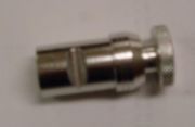
| 09 | Low Pressure Chamber | Tank Adapter | 1 | 1. Allows additional volume to hold gas 2. Seals front end of vertical adapter | Anodized Aluminum | Turned on Lathe | |
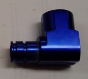
| 10 | Vertical Adapter | Tank Adapter | 1 | 1. Creates a 90 degree elbow from main body 2. Connects expansion chamber (or tank) to main body 3. Allows access to the valve assembly 4.Threaded for attachment of low pressure chamber | Anodized Aluminum | Milled and turned on Lathe | |
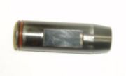
| 11 | Valve Body | Air Valve | 1 | 1. Provides seal surface for the cup seal 2. Transports air to the bolt when cup seal is opened | Aluminum | Turned on Lathe, milled and drilled | |
| 12 | Valve Cup Seal & Pin | Air Valve | 1 | 1. Seals valve when pressurized 2. Slides open when hit by striker allowing air flow | Stainless Steel Pin and Nylon Seal | Pin turned on Lathe and Milled Flat, Seal turned on Lathe | |
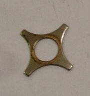
| 13 | Valve Cup Seal Guide | Air Valve | 1 | 1. Keeps valve pin and seal in line while moving 2. Open edges allow air flow around guide 3. Contact surface for valve spring | Plated Steel? | Stamped? | |
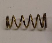
| 14 | Valve Spring | Air Valve | 1 | 1. Holds valve seal closed 2. Controls opening and closing of valve | Alloy Steel Wire | Wound wire | |
| 15 | Ball Detent & Cover | n/a | 1 | 1. Holds paintball in place before struck by bolt 2. Cover holds the rubber detent itself and screws onto main body | Anodized Aluminum Cover and Rubber Detent | Extruded and Milled cover with drilled holes and injection molded detent | |
| 16 | Bolt | Bolt & Striker | 1 | 1. Connects to the striker by steel pin 2. Allows gas flow from below through the bolt to the ball 3. Propels paintball 4. Coloring and grooving for aesthetics | Anodized Aluminum outer section with stainless steel inner piece and pin | Turned on Lathe and Drilled Outer piece, milled inner piece, turned pin, press fit pin | |
| 17 | Striker | Bolt & Striker | 1 | 1. Strikes the valve pin to open valve 2. Drives bolt forward and back 3. Surface for striker spring 4. Directs air from valve to bolt 5. Shaped to hook on trigger mechanism in trigger frame in "cocked" position | Steel | Turned on Lathe and Milled Flat, Black Oxide Finish | |
| 18 | Striker Spring | Bolt & Striker | 1 | 1. Drives striker into valve pin | Steel wire | Wound wire | |
| 19 | Striker Buffer | Bolt & Striker | 1 | 1. Prevents impact between striker and velocity adjuster | Rubber | Extruded and Cut | |
| 20 | Striker Spring Guide | Bolt & Striker | 1 | 1. Keeps spring in-line with striker 2. Provides contact surface for velocity adjustment | Hard Plastic | Injection Molded | |
| 21 | Velocity Adjuster | Bolt & Striker | 1 | 1. Thumbscrew allows easy velocity adjustment 2. Set screw provides velocity "lock" 3. Adjusts length of spring to adjust range of motion and air flow by way of the striker 4. Indented for quick disconnect pin | Anodized Aluminum | Turned on Lathe with Milled Slots and Holes | |
| 22 | Quick Disconnect Pin | Bolt & Striker | 1 | 1. Holds bolt and striker assembly in main body 2. Has hoel in end for locking pin | Stainless Steel | Turned on Lathe and Drilled Hole | |
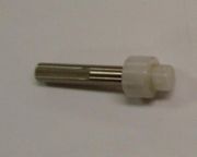
| 23 | Powerfeed Plug | n/a | 1 | 1. Plugs bottom side of ball feed 2. Rotates 180 degrees to turn flow of paintballs on and off 3. Fully removes for cleaning | Plastic | Injection Molded |
Exploded View of Paintball Marker Components
Design Analysis
Design for Manufacturing and Assembly - DFMA
Already Well-Designed Features
1.This is a design built from a "line" of markers, it shares many of the same main parts found in the rest of the line:
- This repeatability is very useful in cutting cost, it requires fewer production lines
- The Grip and trigger frame is used universally across many of the available models of this generation of Spyder marker
- The Main Body was used across all of the Spyder markers, the milling and the powerfeed are the only things that may change between models
- The barrel threads are universal across Spyder markers and also fit some other brands as well - allows for customization
- Most of the exterior or main parts are built for flexibility and customization - user could purchase the lowest end model and customize it into the high end model easily
2. The trigger frame is assembled in a permanent manner with press fit pins
- This reduces the number of screws and fasteners needed in assembly
- The pins also serve a dual purpose in securing the internal moving parts
3. In-Line assembly of bolt and striker
- The back half of internals (the bolt and striker assembly) are installed in-line and held in by a single quick disconnect pin
- This makes disassembly fast and tool-less
Failure Mode and Effects Analysis - FMEA
Design for Environment - DFE
1. For paintball in general, paintballs are completely biodegradable
2. The only parts of a paintball marker that would have environmental effect would be damaged o-rings that are thrown away and the oil used for lubrication, both of which are necessary but minimal
3. The marker is powered by CO2 which is released into the atmosphere
- There is an alternative of compressed air, which is primarily nitrogen and is more environmentally friendly
- The amount of CO2 actually being released is minimal
