Scooter innovation
From DDL Wiki
Contents |
Executive Summary
Market Analysis
Design Documentation
House of Quality
Design Analysis
In the first phase of our project, we analyzed a competitor's product -- the Razor A Scooter -- for its manufacturing and assembly design, failure modes, and environmental effect. The Razor scooter had a few areas of improvement, including minimization of unnecessary parts, standardization of components, creation of multifunctional parts, decreasing of secondary & finishing operations, and ease of handling of parts for assembly in DFMA. The three main possible failure modes we foresaw were hard braking causing deterioration of the wheels, the wheel axle bending due to excess weight or stress, and the collapsing mechanism getting stuck due to environmental factors. From a DFE standpoint, the environmental impact of use is negligible, so the main areas of improvement were in using more environmentally friendly materials, and eliminating manufacturing processes to save energy during production.
In our final design, we have improved on these shortcomings. ...
DFMA
FMEA
In our analysis of the Razor scooter, we identified a number of different potential failure modes in using the competitor product. These failure modes can be found in the table below. This analysis was done using the FMEA method from section 14.5 of Dieter and Schmidt’s Engineering Design. By determining which failure modes have the highest RPN, we can determine which failure modes we need to pay extra attention to while redesigning or creating a new design.
The design of the competitor's product is generally very good from an FMEA standpoint. However, our FMEA showed that the failure of the three areas of most concern with the design of the scooter are the braking system, the axles for the wheels, and the collapsing mechanism. Of these the braking system is the largest problem, because it frequently creates flats on the wheels. This could be solved by redesigning the braking system to prevent or reduce the likely hood of locking the wheels while braking.
The second highest RPN is for the axles, which results from them being an important component of the design as well as being vulnerable to incorrect usage of the scooter. The possible improvements to the axles are limited to improving the materials to increase their strength or clearly labeling the maximum weight that the scooter is designed for.
The collapsing mechanism is an important component and had the third highest RPN value. Possible improvements to the mechanism are mostly limited to redesigning it to use fewer and more durable parts which should make it more reliable.
DFE
Mechanical Analysis
Prototype Documentation
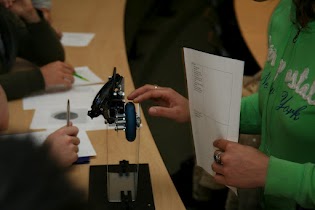
The main purpose of our first prototype was to show the feasibility of attaching a disc brake to the rear wheel of a scooter given existing space constraints. We created a steel disc and an attachment system to connect it to the rear wheel. We purchased a hydraulic bicycle disc brake caliper to integrate into our prototype, and kept the whole system suspended in a metal frame.
Picture by [J Michalek ]
From the first prototype, we learned that any existing calipers will be too large, as they are designed to fit on bicycles or cars, and our volume envelope is much smaller. Feedback on our first prototype was mostly focused around keeping cost from becoming restrictive, safety issues related to the applied braking force, how the brake would be actuated, and keeping the disc brake small.
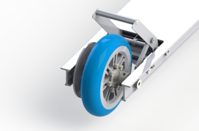
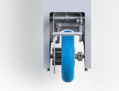
Going forward based on our teammate's feedback, our second prototype focused on designing a foot pedal and a unique, small caliper. Our design employed an l-shaped caliper that rests in front of the wheel instead of next to it, to save space. A hand brake would have caused issues of routing cables, and a foot brake can be used in a similar manner to the brake our competitor uses, with the user's rear foot pressing a bar down over the wheel. Our brake, however, does not press directly on the wheel, so should not cause it to stop completely and degrade from sliding along the ground. The deck we constructed could be integrated into the front wheel and handlebars assembly of our competitor's product in order to be tested.
Our second prototype was fully functional, and demonstrated the feasibility of a foot-actuated brake, as well as a small caliper that fits within the deck of our scooter. Some problems that our user feedback from our second prototype illuminated were that the brake was not intuitive to use (users sometimes stepped on the wheel instead of the brake pedal), and the spring force on the brake felt too weak. We also needed to finalize our brake pad material and strength, and complete calculations of friction force and braking force, as well as estimate stop times for our brakes.
Going forward with our third prototype, we elongated our brake pedal, as well as changing the angle at which it rests, so it is much easier for users to actuate the brakes without excess effort. We also experimented with different materials for our brake pad. We discovered that we ideally wanted the brakes to slow the scooter without stopping the wheel, and still have a stop time of 2-3 seconds. This will eliminate the problem of wheel degradation while allowing for smooth and safe stopping. In a case where an emergency stop is needed, users will jump off the scooter, as they do on our current competitor's product. Having brakes that stop on a dime would actually decrease the safety of our product significantly, and could cause users to injure themselves.
Our first brake design simply had a steel caliper on a steel disc, and did not provide enough of a friction force. It also caused a horrible sound when used, and started to grind away at the disc with very little use. Our second design used neoprene rubber, which provided a perfect friction force, but tore off of our caliper after one use. We experimented with plastics such as Delrin, but even when the surface was roughened, the friction force was so nominal that the scooter hardly slowed at all when the brakes were applied.
We finally applied...
Design Process
Appendices
Appendix A: Bill of Materials
Appendix B: FMEA Data from Phase 1
| Item and Function | Failure Mode | Effects of Failure | S | Causes of Failure | O | Design Controls | D | RPN | Recommended Actions |
|---|---|---|---|---|---|---|---|---|---|
| Upper Head Tube (steering) | Pin that keeps tube telescoped fails, collar continues to have no purpose | Handle bars can detach from scooter, could cause crash | 7 | Stress in pin, low force in collar | 1 | Perform stress tests on the pin | 4 | 28 | Add a warning label on the scooter to keep collar tightened |
| Upper Head Tube (steering) | Button to lock tube in place sticks or brakes | Tube cannot reach full height | 4 | Spring fatigue or dirt/mud affecting button or spring | 2 | Perform fatigue tests on the spring | 3 | 24 | Include cleaning instructions in user manual |
| Collapsing Mechanism (folding for storage) | Spring, lever, or tensioner jams | Collapsing mechanism gets stuck in one position | 4 | Dirt/mud inside the assembly | 3 | Guides for the tensioner are designed to keep dirt out of the assembly | 3 | 36 | Include cleaning instructions in user manual or reduce the number of components that could get stuck |
| Collapsing Mechanism (folding for storage) | Spring brakes or comes loose | Collapsing mechanism no longer locks the scooter open or closed | 6 | Fatigue of the spring or guides failing to keep tensioner aligned | 1 | Perform fatigue testing on the spring | 2 | 12 | none |
| Axel (allows wheels to rotate) | Axel bends | Wheels will stop rolling smoothly or turning completely | 4 | Excessive load on the wheels caused by heavy rider or performing tricks | 5 | Test the effects of fatigue and stress on axles | 2 | 40 | Use a stronger material for axles and add a waring for maximum weight. |
| Wheel Bearings (allows wheels to rotate) | Bearing brakes or jams | wheels stop rotating | 6 | Damage to bearings in a crash or dirt clogging the bearings | 2 | Check for damage to bearings and use sealed bearings | 1 | 12 | Make bearings easier to replace |
| Urethane Wheel Tread (traction for the wheel) | Rips, tears, and gouges in the tread | Prevents smooth riding of the scooter | 4 | Riding on rough terrain | 4 | Perform tests on the durability of the wheel treads | 2 | 32 | Use a stronger material for the wheel treads |
| Rear Wheel Tread (traction for the wheel & braking) | Flat surfaces formed on the surface of the wheel. | Prevents smooth riding of the scooter | 3 | Braking too hard and causing rear wheel to lock. | 7 | Test wear and durability of the rear wheel tread. | 3 | 63 | Use a stronger material for the rear wheel tread or redesign the braking system |
| Lower Tube Subassembly (steering) | Bearing gets jammed | Loose ability to steer scooter | 7 | Damage to bearing in a crash or dirt clogging the bearing | 2 | Check for damage to bearings | 1 | 14 | Improve the design to better seal the bearing |
| Collar from Lower Tube Subassembly (steering) | Collar too loose or threads get stripped | Steering becomes difficult or impossible, could result in crash | 7 | Loosening of screw, over tightening of screw, or damage to the collar | 3 | Check that collar is not loose | 1 | 21 | Include warning that all screws should be tight |
| Handle Bars (steering) | Elastic cable connecting handle bars brakes | Can lose handle bars | 2 | Excessive force on elastic cord or knot in cord comes loose | 5 | Test cord strength | 1 | 10 | Do not use a granny knots to connect handles |
| Handle Bars (steering) | Button connectors stop working | Handle bars won't stay attached | 5 | Spring fatigue or dirt/mud preventing making it difficult to use | 2 | Perform fatigue tests on springs | 3 | 30 | Make springs easy to clean |
| Handle Bar Padding (Makes grip on handle bars more comfortable) | Padding gets cut, scratched, or otherwise damaged | Grip becomes less comfortable | 1 | Not storing scooter properly, crashes, or normal use | 5 | none | 1 | 5 | none |
| Decorative Plastic End Covers (cover sharp edges) | Plastic covers could fracture or get knocked loose | Some sharp edges could be exposed and product would be less visually appealing | 1 | Fatigue or damage from normal use | 5 | Check that end covers are attached | 3 | 15 | Remove the end covers since they are mostly unnecessary |


