Steering rack
From DDL Wiki
(Update Image Filenames) |
|||
| Line 1: | Line 1: | ||
==Functionality== | ==Functionality== | ||
| - | [[Image: | + | [[Image:AssemblySub3_SteeringRack.JPG|1024px]] |
| Line 9: | Line 9: | ||
==Bill Of Materials== | ==Bill Of Materials== | ||
| - | [[Image: | + | [[Image:Assembly10_SteeringRack.JPG]] |
Figure 1: Steering Rack Sub Assembly | Figure 1: Steering Rack Sub Assembly | ||
| Line 22: | Line 22: | ||
|- | |- | ||
| 001 | | 001 | ||
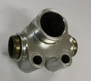
| - | |Pinch Gaurd||2||64||Protects Pinch Points||Extruded, Welded, and Milled||Aluminum||[[Image: | + | |Pinch Gaurd||2||64||Protects Pinch Points||Extruded, Welded, and Milled||Aluminum||[[Image:PGaurd6_SteeringRack.JPG|300px]] |
|- | |- | ||
| 002 | | 002 | ||
| - | |Clevis||2||33||Connects steering rack to tie rods||Milled||6061 Aluminum||[[Image: | + | |Clevis||2||33||Connects steering rack to tie rods||Milled||6061 Aluminum||[[Image:Clevice1_SteeringRack.JPG|300px]] |
|- | |- | ||
| 003 | | 003 | ||
| - | |5/16-24 Bolt <br>(Standard Purchase)||2||13||Bolts clevis to steering rack||Forged||Steel||[[Image: | + | |5/16-24 Bolt <br>(Standard Purchase)||2||13||Bolts clevis to steering rack||Forged||Steel||[[Image:516Bolt_SteeringRack.JPG|300px]] |
|- | |- | ||
| 004 | | 004 | ||
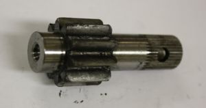
| - | |Pinion||1||99||Convert rotational motion to translational motion||Machined||Steel||[[Image: | + | |Pinion||1||99||Convert rotational motion to translational motion||Machined||Steel||[[Image:Pinion7_SteeringRack.JPG|300px]] |
|- | |- | ||
| 005 | | 005 | ||
| - | ||Rack||1||167||Works with pinion to convert motion. Connects left and right toe links||Machined||Aluminum||[[Image: | + | ||Rack||1||167||Works with pinion to convert motion. Connects left and right toe links||Machined||Aluminum||[[Image:Rack2_SteeringRack.JPG|300px]] |
|- | |- | ||
| 006 | | 006 | ||
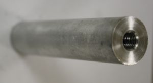
| - | |Extension||2||~71||Extend rack to reach tie rods||Extruded and Lathed||Aluminum||[[Image: | + | |Extension||2||~71||Extend rack to reach tie rods||Extruded and Lathed||Aluminum||[[Image:Extens3_SteeringRack.JPG|300px]] |
|- | |- | ||
| 007 | | 007 | ||
| - | |Set Screw<br>(Standard Purchase)||1||<1||Retains primary bushing||Tapped||Steel||[[Image: | + | |Set Screw<br>(Standard Purchase)||1||<1||Retains primary bushing||Tapped||Steel||[[Image:SetScrew1_SteeringRack.JPG|300px]] |
|- | |- | ||
!Sub-Assemblies* | !Sub-Assemblies* | ||
|- | |- | ||
| 001 | | 001 | ||
| - | |Retaining Block/Mounting Block||1||189||Retains primary bushing||CNCed||Aluminum||[[Image: | + | |Retaining Block/Mounting Block||1||189||Retains primary bushing||CNCed||Aluminum||[[Image:MountBlock4_SteeringRack.JPG|300px]] |
|- | |- | ||
| 002 | | 002 | ||
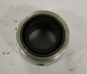
| - | |Pinion Bushing||1||21||Smooths pinion rotation||Machined, Extruded, and Assembled||Aluminum, Bronze, Rubber, and Steel||[[Image: | + | |Pinion Bushing||1||21||Smooths pinion rotation||Machined, Extruded, and Assembled||Aluminum, Bronze, Rubber, and Steel||[[Image:PinionBushing_SteeringRack.JPG|300px]] |
|} | |} | ||
| Line 56: | Line 56: | ||
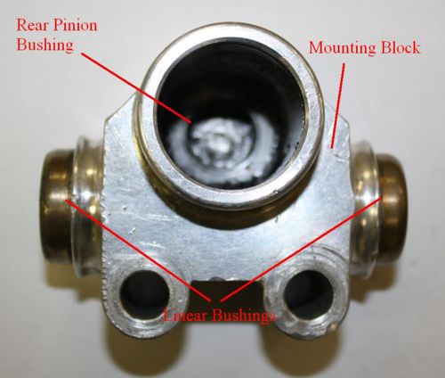
| - | [[Image: | + | [[Image:MountBlockSub_SteeringRack.JPG|500px]] |
Figure 1: Retaining Block sub-assembly with components labeled. | Figure 1: Retaining Block sub-assembly with components labeled. | ||
| Line 62: | Line 62: | ||
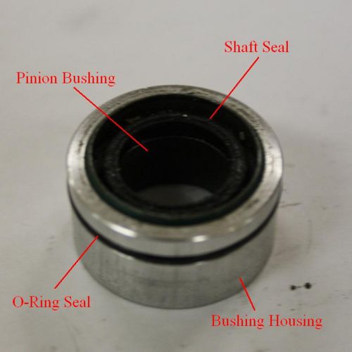
| - | [[Image: | + | [[Image:PinionBushingSub_SteeringRack.JPG|500px]] |
Figure 2: Pinion Bushing sub-assembly with components labeled. | Figure 2: Pinion Bushing sub-assembly with components labeled. | ||
Revision as of 19:56, 20 September 2009
Functionality
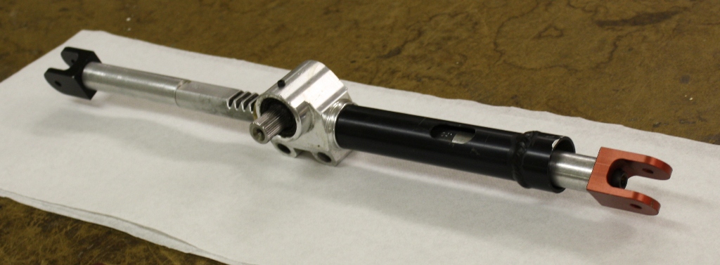
The steering rack produces linear motion from an applied torque to the pinion. The teeth on the pinion engage those on the rack which translates linearly between two bushings. The rack has extensions and clevises to reach the tie rods on the chassis which in turn rotate the wheel, thus steering the car. The pinion is designed to attached to a steering wheel so that the driver need not grip and turn the pinion directly, as they would be able to produce little torque.
Bill Of Materials
Figure 1: Steering Rack Sub Assembly
This assembly was originally a stock Prowerks Aluminum Steering Rack altered by Carnegie Mellon's Formula Society of Automotive Engineers to better fit an FSAE race car. We then disassembled their altered steering rack into its individual components and sub-assembilies. The components, and some basic information about each one, are listed below.
` *Sub-Assembilies were not deconstructed further. It was decided that doing so would result in the destruction of some components with little or no knowledge gained.
Figure 1: Retaining Block sub-assembly with components labeled.
Figure 2: Pinion Bushing sub-assembly with components labeled.

