Tie rack calculations
From DDL Wiki
Contents |
Summary of Calculation Results
Calculations proved that the gear train in the rotating tie rack is used to decrease speed and increase torque provided by the motor. The mechanical advantages of these ratios are that the ties rotate at a speed slow enough to be easily visible to the user, yet with enough torque that rotation occurs regardless of the weight of the ties or interferences with the belt from closet items.
In conclusion, it was determined that the output gained from the input is optimized to meet design goals for the rotating tie rack, and any changes to the mechanisms of the system would be altering the size and number of gears. However, this is also optimized in that there are no mechanical, cost-savings or material advantages to changing the components of the gear train.
The values below summarize the results calculated using the following analysis:
Motor Speed: ω1 = 51314.84 RPM
Motor Torque: τ1 = 0.0284 N-m
Output Speed: ω10 = 70.26 RPM
Output Torque: τ10 = 138.28 N-m
Diagrams
Gear Train
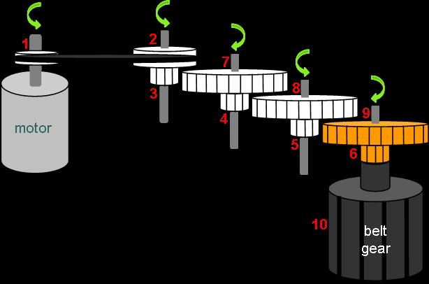
The figure below represents the gear train located in the rotating tie rack. The numbers represent each step of the gear reduction from the motor input (1) to the belt gear output (10) which drives the rotating belt for hanging ties. These numbers are used as subscripts in the speed and torque calculations to differentiate each step, and the arrows indicate the direction of rotation for each shaft. Thus, the rotational velocities calculated are in these corresponding directions.
Free Body Diagram
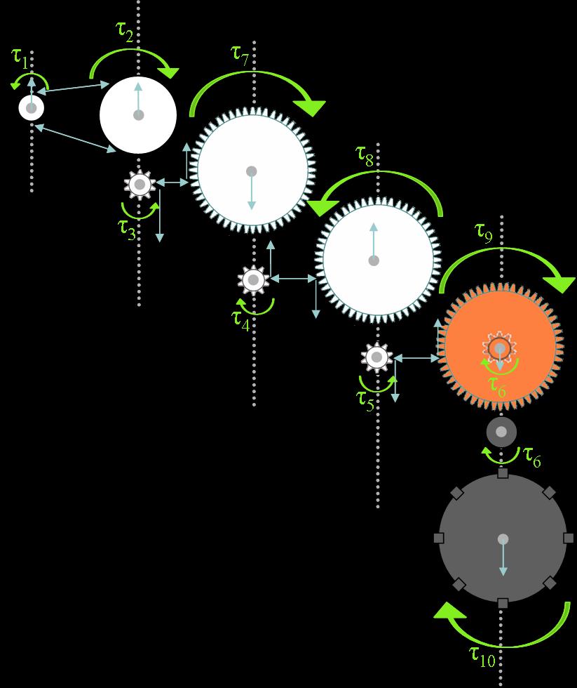
The following free body diagram is also useful, while it is not necessary for the speed and torque values desired for the design. The green arrows again indicate the direction of rotation for each shaft (dotted line), and input (τ1) and output (τ10) torque are the important values which were analyzed. The blue arrows indicate reaction forces, including forces on the gear shafts, from meshing gear teeth and between the gear belt and pulleys. These forces were not calculated as there are not relevant to the analysis and design considerations being pursued.


