Tolerance analysis
From DDL Wiki
| Line 10: | Line 10: | ||
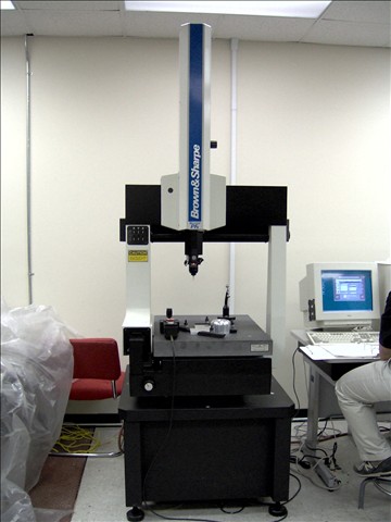
[[Image:CMM.jpg]] | [[Image:CMM.jpg]] | ||
| - | CMMs use 3 axes in order to reach points on a three dimensional surface, with a probe on the third axis. The CMM calculates where a point is in space by reading the displacement of the probe in all the axes and calculating the mathematical offset of the diameter of the tip at every point (DEA 1995 a). | + | CMMs use 3 axes in order to reach points on a three dimensional surface, with a probe on the third axis. The CMM calculates where a point is in space by reading the displacement of the probe in all the axes and calculating the mathematical offset of the diameter of the tip at every point (DEA 1995 a). There are four different types of CMMs commonly used in industry, each with its own advantages and disadvantages: |
| + | |||
| + | 1.Gantry Type | ||
| + | 2.Cantilever Type | ||
| + | 3.Bridge Type | ||
| + | 4.Column Type | ||
Revision as of 13:35, 7 September 2007
Introduction
Manfactured parts are often a conglomerate of basic shapes. While standards are set for specific qualifications in form tolerance analysis, no official methodology exists outlining how to perform such analysis (Samuel et al., 2003). This disparity results in different procedures and techniques for different parts, leading to a possible poor fit and unnecessary scraping of expensive materials. One of the primary machines used to evaluate tolerances of products are Coordinate Measuring Machines (CMMs).
Coordinate Measuring Machine (CMM)
As defined by Busch (1989), coordinate measuring machines (CMMs) locate coordinates on three dimensional structures while simultaneously integrating both the x-y plane and z-plane along with orthogonal relationships. CMMs then utilize a computer and companion software to analyze and interpret measurement results (Dhanish, 2002).
CMMs use 3 axes in order to reach points on a three dimensional surface, with a probe on the third axis. The CMM calculates where a point is in space by reading the displacement of the probe in all the axes and calculating the mathematical offset of the diameter of the tip at every point (DEA 1995 a). There are four different types of CMMs commonly used in industry, each with its own advantages and disadvantages:
1.Gantry Type 2.Cantilever Type 3.Bridge Type 4.Column Type
Advantages
Busch (1989) states that such a device has several advantages in a quality-control setting when combined with certain criteria, such as:
1. Multiple features-when there are several geometric features being controlled
2. High unit cost-if destructive inspection is not viable, then a CMM is the less costly alternative
3. Production interruption-CMM inspection will not cause downtime in machining
Limitations
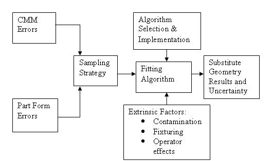
However, Phillips et al. (1998) points out that CMM hardware accumulates error in addition to the error of the object of interest. The researchers generated a schematic illustrating error aggregation in CMM measurement:
Figure 1 explains error aggregation that may occur during data collection.
When evaluating sampling strategies, not only are part errors accumulated but also CMM errors, i.e. failure to calibrate the machine, axis displacement, machine repeatability, etc. Though sampling strategy is intended only to calculate part form error, CMM error is inadvertently calculated as well. The end result is an approximation that incorporates form and CMM errors that cannot be separated.
Sample Products


