Vacuum cleaner
From DDL Wiki
(→Quantitative Mechanical Analysis) |
(→Product Uses) |
||
| Line 20: | Line 20: | ||
-Turn off unit<br\> | -Turn off unit<br\> | ||
-Wind power cord and store<br\> | -Wind power cord and store<br\> | ||
| + | |||
| + | The normal use of a household vacuum cleaner can be seen in the flow chart below. | ||
| + | |||
[[Image:dirtdevilflowchart.jpg]] | [[Image:dirtdevilflowchart.jpg]] | ||
Revision as of 00:52, 24 September 2007
Contents |
Executive Summary
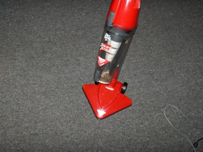
During our product analysis of a Dirt Devil Swift Stick we came across several notable observations. As we went through the uses of the product and used them for its main function a few basic problems occured. These problems ranged from small annoyances to major hazzards. This caused us to further look into customer needs and how they can be addressed for this product. Once the product uses and customer needs were completely documented the product was dissected and all of the parts were analysed and documented in detail. This gave us a more complete understanding of how this product was manufactured and assembled. The dissection gave us a basis for further analysis. This further analysis included DFMA, FMEA, DFE, and Quantitative Mechanical Analysis. From these analyses, decisions could be made to improve upon any areas of manufacturing that could be lacking or cause ill effects on the environment.
Product Evaluation
During product evaluation our group used the vacuum cleaner in an everyday use situation. We noted things that worked well along with external problems that occured with everyday use.
Function
A vacuum cleaner is common household appliance used for cleaning purposes. A vacuum cleaner cleans by creating suction. A pump creates a pressure difference inside the unit causing atmospheric air to be forced up through a tubing system. Most vacuum cleaners utilize a rotating brush at its entrance to help "sweep" dust and dirt into the suction path. Vacuumed particles are finally depostited in some collecting container that can either be removed or emptied after use.
Product Uses
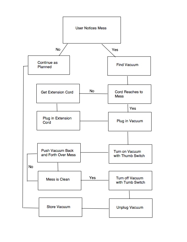
For normal use of a vacuum cleaner:
-Unwind power cord and connect unit to home outlet
-Power on unit
-Move unit in back and forth motion covering the vacuum area desired
-Turn off unit
-Wind power cord and store
The normal use of a household vacuum cleaner can be seen in the flow chart below.
Customer Needs
The traditional user needs for a vacuum cleaner are:
-Ability to provide suction
-Effective cleaning ability
-Comfortable use while operater is standing
-Easy removal of dirt/dust container
-Durability
-Easy Storage
-Fair cost
Bill of Materials
An extensive list of parts in the vacuum. Information includes part names, quantities, weights, function of use, process for manufacturing, and the material the parts are made from.
Product Analysis
In depth analysis of the individual parts and function of the vacuum. This allowed for more discussion for possible improvement to the existing product. Improvements were found in the areas of manufacturing, failure, and environment.
Design for Manufacturing and Assembly
Design for Manufacturing and Assembly (DFMA) is a set a of tools and methods for analyzing the manufacturing process in order to develop a simplified process of reduced cost.
Current DFMA
The current product has most likely been through an extensive improvement process. Nearly all of the parts of the vacuum has only one possible fit so there is no opportunity for confusion or mistakes. Making the design even better is the inclusion of notches between fitting parts. The addition of notches allow for correct pieces to easily slide together into the correct position.
There are a few areas that could be improved.
Recommended Improvements
The current design requires many screws to be used for assembly. This process can be improved with a redesign utilizing snaps to fasten the product. Snaps would make assembly easier and faster but also more robust. A vacuum's operation experiences many vibrations. These vibrations can lead to eventual losening of the screws. The use of snaps would eliminate the potential for this problem.
Another problem with the current design is the process of attaching the power cord. The current design has multiple ambiguous positions for placement of the cord. It is the one part where this occurs. This process can be easily simplified by merely adding a color code or the elimination of the multiple choices.
Finally, there were a few different screws used in the assembly. There was not a major difference between the different types which could possibly lead to some mistakes or confusion when deciding which component to use. Making the screw types more identifiable with there correct position could further aid assembly. Elimination of screw elements would also solve this problem.
Failure Mode Effects Analysis
| Item and Function | Failure Mode | Effects of Failure | S | Cause of Failure | O | Design Controls | D | RPN | Recommended Actions | Responsibility & Deadline | Actions Taken | S | O | D | RPN |
|---|---|---|---|---|---|---|---|---|---|---|---|---|---|---|---|
| Vaccum Channel *Creates channel for vaccum flow | Jams/Clogs | No air flow | 4 | Objects jammed at inlet | 5 | Product testing in normal situations | 3 | 60 | Explore other inlet design options | N/A | N/A | 4 | 5 | 3 | 3 |
| Wheel *Allows vaccum to roll | Jammed/Stops turning | Vaccum can no longer roll | 4 | Axel dammage | 2 | Quality control testing | 1 | 8 | Take no action | N/A | N/A | 4 | 2 | 1 | 8 |
| Motor/Blower *Provides air flow | Blower stops turning | Fials to produce suction | 6 | Missing filter/hole in filter causes debris to damage moter/blower | 2 | Test use when filter is damaged | 2 | 24 | Take no action | N/A | N/A | 6 | 2 | 2 | 24 |
| Electrical Cord *Provides power to motor | Does not fit properly into electrical outlet | No electrical connection can be made, Potential for electric shock | 8 | Tight fit around electrical outlet | 5 | Failure observed by user | 1 | 40 | Explore other cable/outlet design options | N/A | N/A | 8 | 5 | 1 | 40 |
| Switch activator *Makes circuit connection to provide power turn on motor | Does not make connection | Vaccum will not turn on | 4 | Shaft does not line up due to wear | 1 | Quality testing by pushing button Extended life testing | 3 | 12 | Explore more durable materials | N/A | N/A | 4 | 1 | 3 | 12 |
Design for Environment
Design for environment (DFE) is method for analyzing the environmental impact of a product. DFE considers a product’s manufacturing processes as well as its use throughout the product’s life cycle.
The environmental impact of a product can be determined through a process called EIO-LCA. This process takes into account all sectors of the econonmy affected by the manufacturing and distribution or the specified product. The EIOLCA software determines the impacts of economic activity, energy usage, greenhouse gas emissions, employment, etc.
For our product we evaluated the economic impact as well as the energy usage for the products life cycle. Using the software we evaluated the economic impact of a household vacuum production for 1 million dollars of economic activity. It was determined that 2.3 million dollars total is needed for production. Using the price of a single vacuum, (30 USD,) we determined the per unit price of manufacturing to be 69 USD. In addition to the evaluation of manufacturing economic impact, we evaluated the impact of electrical use. For our unit we estimated the use to be 100 hr/year. This value considers home use as well as use by cleaning professionals. With the vacuum rating and our electrical supplier’s kw-hr price, the cost for a year of operation is 117 USD/year. Other enviromental effects were also considered and can be seen at EIOLCA Results
Economic Activity
| Sector | Total Economic $mil | Value Added $mil | Direct Economic $mil | Direct % | |
|---|---|---|---|---|---|
| Total for all sectors | 2.30 | 0.987 | 1.62 | 70.4 | |
| 335212 | Household vacuum cleaner manufacturing | 1.00 | 0.375 | 1.00 | 100.0 |
| 420000 | Wholesale trade | 0.096 | 0.064 | 0.050 | 52.4 |
| 550000 | Management of companies and enterprises | 0.072 | 0.051 | 0.039 | 53.9 |
| 325211 | Plastics material and resin manufacturing | 0.063 | 0.015 | 0.041 | 64.6 |
| 32619A | Plastics plumbing fixtures and all other plastics products | 0.056 | 0.023 | 0.051 | 91.8 |
Considering purchase of a vacuum occurs an estimated once every three years, the economic impact from the energy has the larger environmental impact. Our design for environmental efforts will pursue a solution for the energy comsumption.
Quantitative Mechanical Analysis
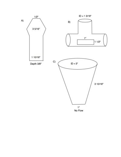
Air flows in the vaccum from the blower to the vaccume outlet. In between, the air flows through parts of the vaccum assembly with different cross sectional areas. The path of air is as follows:
1.) Air is pulled in through the initial vaccum channel (arrow point) (Fig. A)
2.) Air travels through a rectangular cross-sectional channel
3.) Air flows through a circular swivel connector (Fig B)
4.) From the connector, the air travels throgh the waste basket
5.) Air is pulled from the waste basket through a filter (Fig C)
6.) Air is pulled in to the blower inlet
7.) Air pulled through impellar and exhaled out the vent on the motor housing

The airflow, Q, does not change at any point through the vaccum. Airflow is dependent only on the fluid power of the motor/blower assembly. The velocity, however, does change at different points through the flow channels. As the cross-sectional area increases, the velocity of air decreases. As the cross-sectional area decreases, the velocity increases. Suction produced at the outlet is based on the dynamic pressure at that point. Dynamic pressure is directly proporational to the square of the velocity.
If the motor and impellar efficiencies were known, as well as the voltage and current being delieverd to the motor, then the suction pressure could be estimated using the formulas Q=VA where A is the cross-sectional area and V is the air velocity, and q=1/2 rho * V2 where rho is the fluid density and q is the dynamic pressure.


