Weed whacker
From DDL Wiki
(→Failure Mode Effects Analysis (FMEA)) |
(→Failure Mode Effects Analysis (FMEA)) |
||
| Line 143: | Line 143: | ||
| Fouled spark plug | | Fouled spark plug | ||
| Engine won't start | | Engine won't start | ||
| - | | 8 || Spark plug is dirty or broken || 3 || Fatigue testing || 1 || 24 || Approximate the life-span of the spark plug || || - || || || || | + | | 8 || Spark plug is dirty or broken || 3 || Fatigue testing || 1 || 24 || Approximate the life-span of the spark plug || Engine manufacturer || - || || || || |
|- align="center" valign="center" | |- align="center" valign="center" | ||
| Carburetor | | Carburetor | ||
| - | | Engine won't idle || 7 || carburetor not adjusted properly || 3 || Fatigue testing || 1 || 21 || Add more lubricant || | + | | Engine won't idle || 7 || carburetor not adjusted properly || 3 || Fatigue testing || 1 || 21 || Add more lubricant || Engine Manufacturer || - || || || || | |
| Line 180: | Line 180: | ||
| Slip | | Slip | ||
| Reduced control when holding | | Reduced control when holding | ||
| - | | 6 || Screws loosen over time || 7 || Fatigue testing || 2 || 84 || Look into improved handle design || | + | | 6 || Screws loosen over time || 7 || Fatigue testing || 2 || 84 || Look into improved handle design || Design Engineer || - || || || || |
|- align="center" valign="center" | |- align="center" valign="center" | ||
| Fracture | | Fracture | ||
| No working handle for off hand | | No working handle for off hand | ||
| - | | 7 || Item is dropped onto handle || 4 || Impact stress testing || 3 || 84 || Look into improved handle design || | + | | 7 || Item is dropped onto handle || 4 || Impact stress testing || 3 || 84 || Look into improved handle design || Design Engineer || - || || || || |
|- align="center" valign="center" | |- align="center" valign="center" | ||
| Fatigue | | Fatigue | ||
| Handle deforms over time, less convenience for user | | Handle deforms over time, less convenience for user | ||
| - | | 5 || Repeated adjustment of handle, use over time || 6 || Fatigue Testing || 3 || 90 || Look into improved handle design || | + | | 5 || Repeated adjustment of handle, use over time || 6 || Fatigue Testing || 3 || 90 || Look into improved handle design || Design Engineer || - || || || || |
|- align="center" valign="center" | |- align="center" valign="center" | ||
| Line 194: | Line 194: | ||
| Tangled Wire | | Tangled Wire | ||
| Wire inside head jams up | | Wire inside head jams up | ||
| - | | 8 || Improper wire loading || 3 || Field Testing || 2 || 48 || Ensure easy/intuitive wire replacement process for user || | + | | 8 || Improper wire loading || 3 || Field Testing || 2 || 48 || Ensure easy/intuitive wire replacement process for user || Process Engineer || - || || || || |
|- align="center" valign="center" | |- align="center" valign="center" | ||
| Fracture | | Fracture | ||
| Line 204: | Line 204: | ||
| Jam | | Jam | ||
| Bearing has friction, slows axle down | | Bearing has friction, slows axle down | ||
| - | | 7 || Left in rain, water can reach bearing and rust || 2 || Bearing Testing || 2 || 28 || Ensure bearings are guarded from elements || | + | | 7 || Left in rain, water can reach bearing and rust || 2 || Bearing Testing || 2 || 28 || Ensure bearings are guarded from elements || Assembly || - || || || || |
|- align="center" valign="center" | |- align="center" valign="center" | ||
| Line 210: | Line 210: | ||
| Fracture | | Fracture | ||
| Can't effectively guard user from debris or wires | | Can't effectively guard user from debris or wires | ||
| - | | 5 || Weed Whacker is dropped, shield takes impact || 7 || Stress Testing || 2 || 70 || Design more reliable shield || | + | | 5 || Weed Whacker is dropped, shield takes impact || 7 || Stress Testing || 2 || 70 || Design more reliable shield || Design Engineer || - || || || || |
|- align="center" valign="center" | |- align="center" valign="center" | ||
Revision as of 15:44, 23 September 2008
Contents |
Executive Summary
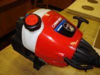
For our Engineering Design II project, we have decided to dissect and improve the 2-Cycle Straight Shaft Trimmer made by Troy-Bilt. We intend to improve its user functionality, the manufacturing process, and also reduce the impact the life of this product has on the environment. We will disassemble this trimmer in order to take a close look at all of its parts. By performing DFMA, FMEA, and DFE, we will carefully document our findings, decisions, and conclusions in order for our client to clearly see the merits in the product we have reinvented.
Stakeholders
There are several stakeholders that will be affected by our changes to this product. They include:
The manufacturer
Fulltime/partime gardeners
Lawn owners
Raw material suppliers
Gardening/home improvement stores
Product Usage
Usage of a weed whacker is very straight forward. For situations and areas where a lawnmower would be difficult to use, the hand-held weed whacker becomes a tool of choice. The convenience of this gardening tool comes from its ability to quickly cut vegetation in hard to reach places without damaging structures that may surround it.
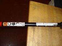
In order to power on the weed whacker, first make sure there is sufficient gas in the tank. Click the on/off switch to on. Intructions on how to start the motor are included on a sticker on the straight shaft, and are as follows:
For a cold engine:
1. Press bulb 10 times.
2. Move blue choke lever to "1".
3. Squeeze trigger and pull rope 5 times.
4. Move blue choke lever to "2".
5. Squeeze trigger and pull rope till engine starts. If it doesn't start, repeat steps 1-5.
6. Let engine run 15-30 seconds.
7. Move blue choke lever to "3".
For a warm engine:
1. Move blue choke lever to "2".
2. Squeeze trigger and pull rope till engine starts.
3. Move blue choke lever to "3".
Once the engine is running, it is a simple matter of pointing the spinning wire towards the vegetation you wish to cut. If you wish to lengthen the wire, tap the bottom of the weed whacker to the ground, and a pre-measured length of wire will be added on. To stop the motor, simply press and hold the off button.
System Functions
After starting the engine, the weed whacker is controlled by a single trigger. This trigger controls the fuel feed to the engine allowing the user to change the rotational speeds of the two-cycle engine.
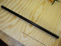
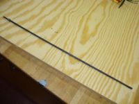
The power of the engine is transferred to an axle contained in the upper shaft. The axle is held in the center of the shaft using spacers. The end of the upper axle is shaped to slip over the end of the lower axle. The two axles connect using a square cross section that allows the power from the upper axle to completely transfer to the lower axle. To compensate for the possibility of misalignment, the two axles are made to be flexible.
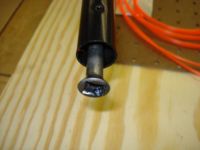
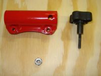
The lower shaft is held to the upper shaft using the shaft clamp. This shaft clamp is screwed directly into the upper shaft, and holds the lower shaft by the metal nub.
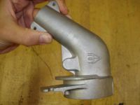
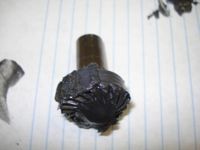
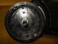
At the bottom of the lower shaft, there is a large metal housing. Within this housing, there are four bearings and a set of bevel gears. The lower axle attaches to the bevel gear in the same manner as the two axles. Two bearings are placed on each end to keep the bevel gears in contact. With the gears, the power transfers completely from the lower axle to the weed whacker head.
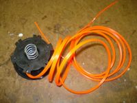
Attached to the weed whacker head, is a reel that contains a long piece of wire. The wire is fed through two small holes exposing approximately 5 inches of wire. While the head is rotating, the wires are used to cut weeds. Due to the high speeds of the wire, there is no need for sharp edges, as the impact from the wire alone is enough to cut through plants.
Components
**Note: Some assemblies and parts were not disassembled in order to avoid destroying the parts.
Failure Mode Effects Analysis (FMEA)
| Item and Function | Failure Mode | Effects of Failure | S | Causes of Failure | O | Design Controls | D | RPN | Recommended Actions | Responsibility and Deadline | Actions Taken | S | O | D | RPN
|
|---|---|---|---|---|---|---|---|---|---|---|---|---|---|---|---|
| Engine | Fouled spark plug | Engine won't start | 8 | Spark plug is dirty or broken | 3 | Fatigue testing | 1 | 24 | Approximate the life-span of the spark plug | Engine manufacturer | - | ||||
| Carburetor | Engine won't idle | 7 | carburetor not adjusted properly | 3 | Fatigue testing | 1 | 21 | Add more lubricant | Engine Manufacturer | - |
| ||||
| Bevel Gears | Slip | Wire doesn't rotate | 7 | gears aren't properly aligned | 3 | Unalign gears and turn on | 6 | 126 | Check how much tolerance the shafts give the rod and gears | - | |||||
| Jam | Wire doesn't rotate | 8 | Not enough lubricant | 2 | Remove lubricant and turn on | 5 | 80 | Add more lubricant | - |
| |||||
| Axle | Fracture | Wire doesn't rotate | 7 | Fatigue | 1 | Fatigue testing | 4 | 28 | Not likely, so ignore | - | |||||
| Wear down | Lower shaft axle won't spin at full potential | 6 | Lower shaft axle doesn't securely mate with upper shaft axle | 4 | Fatigue testing | 5 | 120 | Not likely, so ignore | - | ||||||
| Shaft Clamp | Dent | Shaft wont fit into clamp | 8 | Something heavy dropped onto clamp | 1 | Stress testing | 1 | 8 | Not likely, so ignore | - |
| ||||
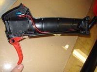
| Handle | Slip | Reduced control when holding | 6 | Screws loosen over time | 7 | Fatigue testing | 2 | 84 | Look into improved handle design | Design Engineer | - | ||||
| Fracture | No working handle for off hand | 7 | Item is dropped onto handle | 4 | Impact stress testing | 3 | 84 | Look into improved handle design | Design Engineer | - | |||||
| Fatigue | Handle deforms over time, less convenience for user | 5 | Repeated adjustment of handle, use over time | 6 | Fatigue Testing | 3 | 90 | Look into improved handle design | Design Engineer | - | |||||
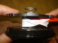
| Head | Tangled Wire | Wire inside head jams up | 8 | Improper wire loading | 3 | Field Testing | 2 | 48 | Ensure easy/intuitive wire replacement process for user | Process Engineer | - | ||||
| Fracture | Cracks or openings in head, inhibiting wire feed or even proper head fit | 8 | Slamming head into rough object while it's spinning | 2 | Field Impact Testing | 2 | 32 | Not likely, so ignore | - | ||||||
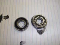
| Bearing | Jam | Bearing has friction, slows axle down | 7 | Left in rain, water can reach bearing and rust | 2 | Bearing Testing | 2 | 28 | Ensure bearings are guarded from elements | Assembly | - | ||||
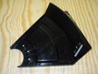
| Shield | Fracture | Can't effectively guard user from debris or wires | 5 | Weed Whacker is dropped, shield takes impact | 7 | Stress Testing | 2 | 70 | Design more reliable shield | Design Engineer | - | ||||
| Trigger | Fracture | Convenient engine control diminished | 5 | Sharp force applied to trigger in wrong direction | 1 | Stress Testing | 2 | 10 | Not likely, so ignore | - |
Design for Manufacture (DFM)
The weed whacker is a relatively simple product simple parts. Being long and tube-like in shape and nature, extrusion would be a process of choice for several of the parts - namely the shafts and axles. We have noticed that the two shafts that connect to each other are different from one another when they do not have to be. By making them identical, they can be manufactured much more quickly.
Injection molding will also be used for the plastic parts, including the handle and the shield. Both of these parts seem to be more complicated than they have to be. The shield for example only needs to be a simple sheet of plastic that covers the appropriate area. Perhaps the additional complexity was added for aesthetics, but they no other apparent purpose. A simpler design here can potentially reduce environmental impact and shorten manufacturing time.
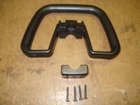
The handle seems to have the same problem as the shield. It is more elaborate than it has to be. However, in this case it can be argued that this design for the handle offers greater comfort for the customer holding the trimmer. Notice how the handle allows you to hold it from the sides. This does not seem practical. Using one hand to hold it from the side in this way would put a significant amount of strain on that hand. The best way to hold it is from the top. Therefore, the handle only needs to be a straight horizontal bar. Perhaps a triangular shaped handle would maintain both user comfort as well as aesthetic appeal. Once again the reduction of material necessary will reduce environmental impact.
Design for Assembly (DFA)
Design for Environment (DFE)
There are two main aspects of this product to scrutinize in order to reduce its impact on our environment - usage and production. Since the mechanics of how a weed whacker works are quite simple, there is little that can be done to reduce waste from the usage of this product. The mechanics that go into a weed whacker are frankly quite simple. From the explaination in the functionality section, it can be seen that there is very little power loss in the mechanical transfer of power from the engine to the rotating wires.
Usage
This particular weed whacker design uses a 2-cycle engine as its power source. This method is harmful to the environment, as it allows unused gasoline and oil to escape as exhaust.
Not only is it emitting a lot carbon dioxide and some hydrocarbons, it is also releasing unburnt gasoline. The gasoline vapors react with the sunlight creating even more carbon dioxide, nitrous oxides, and more volatile organic compounds. The inefficiency of the 2-cycle engine has a very large impact on green house gases and the environment.
Mechanical Calculation
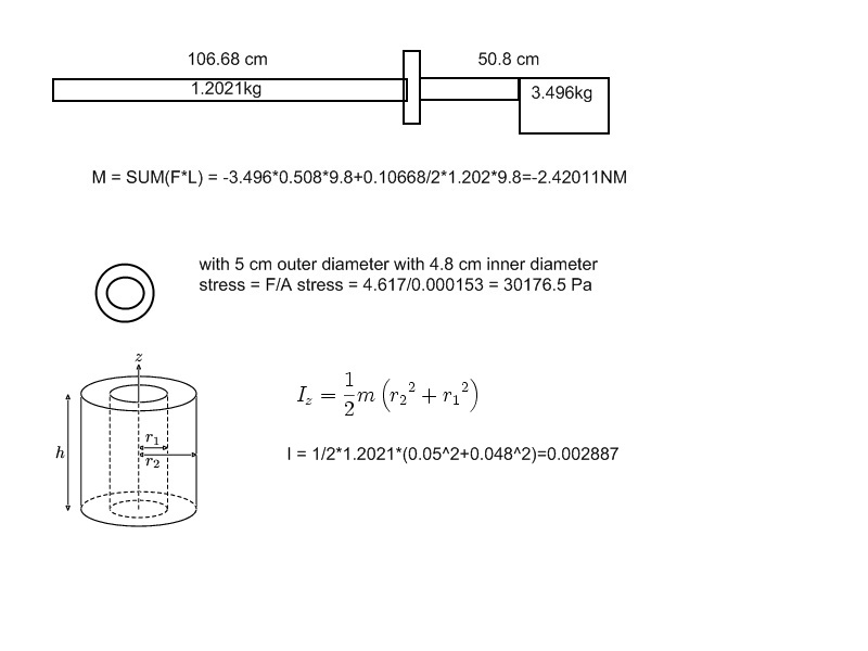
In order to increase the ease of usage of the wheed whackers, parts were assembled in a way that it creates less moments. For example, with engine weighing 4.08233 kg and stick weighning 1.202kg, one is 106 cm and other is 50.8 cm away from the handle, using the formula M = LF, moments of only -2.42011N-M was created.
Another thing that should be taken account is that wheed whacker is build with huge magnitude of safety. Using the formula stress = F/A and A = area of the tube along the diameter, we found that the stress that is applied was 10209 Pa. And since the material of the wheedwhacker is steel, it has yeild strenght of 250 MPA. Which is far above the maximum stress on the wheed whacker. Even if we drop it and apply the force of 100 N to the pole, the calculation still did show that the wheedwhacker could withstand it.
