Airsoft Electronic Ammunition Counter Final Report
From DDL Wiki
Contents |
Executive Summary
In this report, we will present our final product redesign solution as well as an analysis of our product and the prototype. For our consumer product redesign, we analyzed numerous airsoft products and concluded that there was a market need for an airsoft ammunition counter that has not yet been met. The basis behind an airsoft ammunition counter is relatively simple. The counter indicates the number of pellets left in a user's gun.
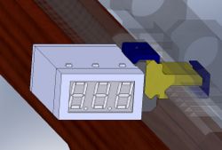
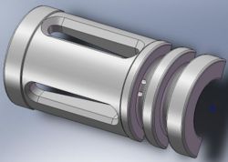
The ammunition counter is an aftermarket airsoft accessory that was design to fit on nearly all airsoft guns with a standard weaver or Picatinny rail. The Airsoft Ammunition Counter is comprised of two part, a flash hider and the counter box. The counter box houses the electronics, the preset and reset buttons, and the LED display. Within the flash hider a photo-interrupter is stored. This photo-interrupter triggers the electronics in the counter so that the number on the LED decrements every time an airsoft pellet passes through the flash hider and leaves the gun.
This report presents a complete set of engineering drawings with detailed dimensions and manufacturing and assembly processes. Following that, a numerical calculation of the photogate circuit is shown. From our numerical calculations, we concluded that the photogate in the integrated circuit would easily be capable of counting accurately.
A prototype of our final design was modeled with a Z-Corp printer so that we may get user feedback. Although our feedback indicates that our ammunition counter design is not complete and another design iteration was necessary, our testers felt that we had a good idea that would well serve the airsoft community.
Airsoft Background
Airsoft is a combat sport very much like paintball. The objective of the game is to eliminate other players by hitting opponents with plastic pellets fired from their airsoft guns. The guns used in airsoft games are replicas of real world guns both in a gun's shape and weight, although most airsoft guns are made of plastic rather than metal like their real world counterparts. Like real guns, airsoft guns fire their ammunition by expelling high pressure gas out the barrel. How this high pressure is created is how the gun is classified. Automatic electric guns (AEGs for short) dynamically create high pressure gas through a motorized spring piston system, while as gas guns simply releases gas stored at high pressure. The ammunition fired from airsoft guns are spherical plastic pellets that have a 6mm diameter and usually weigh anywhere from .20-.25g. These pellets have muzzle velocities between 175-500ft/s which makes them capable of hitting targets over 200ft away.
Airsoft began in Japan in the early 1980s out of necessity. At the time, there was a small market of Japanese sporting enthusiasts who wanted to own guns but could not do so because Japanese law forbids it. Consequently, the Japanese did the next best thing by creating airsoft guns. Airsoft guns allowed the Japanese to come as close as they possibly could to imitating real guns. The realism of airsoft guns is one of the appeals of airsoft. In fact, many airsoft games have been called "milsims" (short for "military simulations") since not only are players carrying realistic looking guns, but players often go to games wearing military fatigues as well as bringing two way radios and other military equipment. The appeal of airsoft's realism goes beyond civilian usage as certain police and military forces have been known to use airsoft guns for training exercises.

Source: http://www.wpairsoft.com/forum/
Opportunity
Ammunition is a fundamental need of an airsoft player. Without ammunition, players can neither eliminate opponents nor can they defend themselves from being eliminated by the opposing team. Airsoft players know that they should avoid running out of ammunition. However, our observations of players at an airsoft event confirmed that players do, on occasion, run out of ammunition prematurely. In fact, our team faced the same ordeal when we played in a few airsoft games. The primary cause of this problem is that it is very difficult for airsoft players to say, with reasonable certainty, how much ammunition they have remaining in their magazines. Some players shake their magazine and listen to the rattling sound made by the remaining pellets in order to get an idea of much ammunition is left in their magazine. This method is not very accurate and actually only works on certain kinds of magazines. The rest of the airsoft players simply guess their remaining ammunition count based on how many times they have fired their gun. This is also a poor way to gauge how much ammunition is left in a magazine.
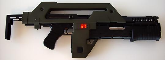
Source: http://www.clayjohanson.com/html/M41-A(1).jpg
To date, there are not really any airsoft products that informs the user about of their ammunition count. The only relevant airsoft product is the M41A Pulse Rifle Kit. This kit converts a Tokyo Marui M1A1 into a M41A replica. In keeping true to a M41A's functionality, the kit includes an LED display that shows a number representing how much ammunition is left in the magazine. This kit may sound like something airsoft players should embrace since the LED display solves the issue of not knowing how much ammunition is in the magazine. However, the reality of it is that this kit is worthless to the majority of airsoft players. The problem with this kit is that it is specifically designed to work only on a Tokyo Marui M1A1. What airsoft players really need is an LED ammunition counter that works on all guns. That is the opportunity we have chosen to pursue.
Design Solution
Overview
Our team has designed an electronic ammunition counter that allows airsoft players to know exactly how much ammunition is left in their magazines. The premise behind our counter is simple: when users want to know how much ammunition is in their magazine, they simply look at the number shown on our counter's LED display. This number represents the number of airsoft pellets currently in the magazine. Our counter is a very convenient product for airsoft games since it runs autonomously while the user fires their gun. The only action required on the user's part, outside of a one time installation and setup, is to hit the reset button when they reload their magazine.
How It Works
When an airsoft pellet is fired, it passes out of the gun's barrel and out through the flash hider. Hidden inside of the flash hider is a photogate sensor. Photogate sensors are electronic components that produce more or less voltage depending on whether or not something is between the light emitting diode (LED) and phototransistor. As for our counter, the photogate sensor in the flash hider is used to detect when airsoft pellets have been fired from the gun. The flash hider has wires leading to the display box. When an airsoft pellet is fired, the display box receives a lesser voltage from the photogate sensor than when no pellet is fired. The electronics inside of the display box recognizes this drop in voltage as meaning that an airsoft pellet has been fired. Consequently, the counting circuit subtracts one from the current magazine ammunition count. The updated ammunition count is then shown on the seven segment LED display.
On the top and bottom of the counter box, there are four buttons; three on one side, one on the other. The lone button is the preset button. When pressed, it will reset the value on the counter to a user defined value. The three buttons on the other side allow the user to change the preset value. Each button corresponds to one digit on the display, either the ones, tens, or hundreds place. Each digit in the presetting mode is independent from the others, meaning that when one digit overflows from 9 to 0, it will not affect adjecent digits. When the preset button is pressed and held while the individual digits' buttons are pressed, the display gives a real-time display of what the preset value is. The counter will not return to its counting mode until the preset button is released.
Engineering Drawings of Components with Assembly Process
This section presents our engineering drawings for each component as well as assembly drawings depicting how each component fits together in relation to each other.
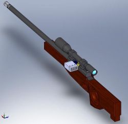
Below is a CAD model of our a Well's L96 airsoft gun with our electronic ammunition counter attached.
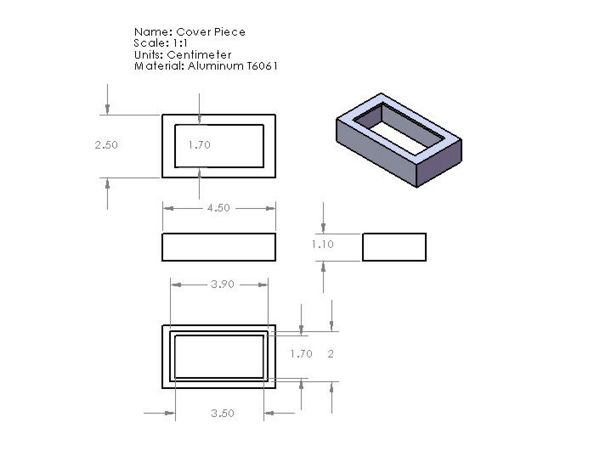
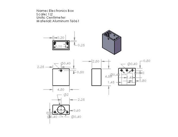
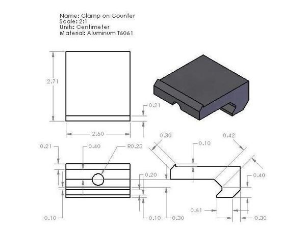
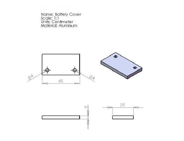
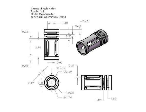
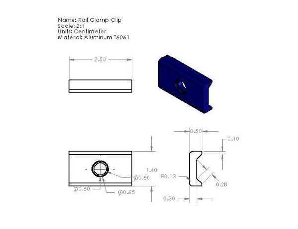
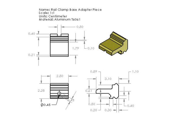
Below are engineering drawings of all manufactured parts
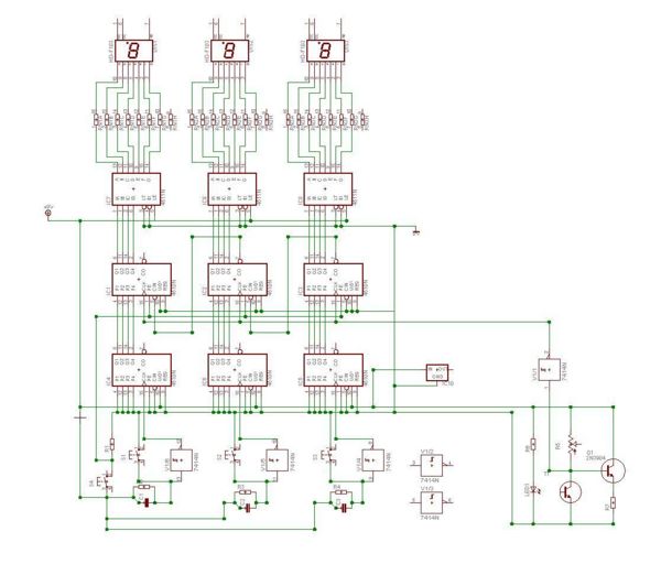
Below is a schematic of our ammunition counter's electronics
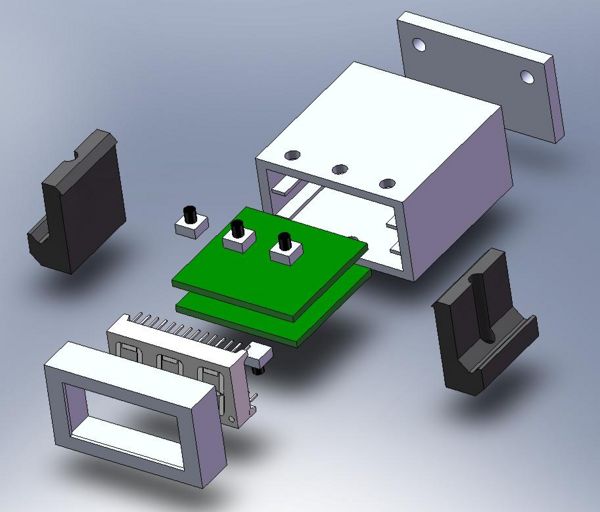
Here is an exploded view of our assembly
The display piece and the battery cover will be attached to the display box by snap fits.
Design for Assembly
From the exploded view of the counter box we see that our design was constructed with Design for Assembly in mind. The base of our assembly is the Display Box. Once it is placed on an assembly line, the display box does not need to be lifted or moved again. Afterwards, the two printed circuit boards can be slided into the rails of the box and secured with an adhesive. The LED display is connected to the printed circuit boards and Display Cover is then screwed onto the Display Box with four corners screws. The clamp bases are mounted onto the left and right side of the counter box and are again secured with screws. Finally the battery cover can be placed on the end of the Display Box.
The clamp clip and the clamp base both exhibit symmetry around a central plane. This allows for the parts to be reused for the left of right side or the counter box thus eliminating the need for two distinct sets of clamps. Reduction in the number of unique parts decreases confusion during the assembly process. The cover piece is another part with 180 degrees symmetry. Our remaining parts are asymmetric and prominently so. For example, one green printed circuit board has three buttons and another has one. This allows for the assembler to quickly distinguish between the two boards and thereby reduces the assemble time.
Manufacturing and Materials
This section summarizes the materials and manufacturing processes necessary for our counter
| Part | Material | Manufacturing Process |
|---|---|---|
| Display Piece | Aluminum | |
| Display Box | Aluminum | |
| Display Box Clamp | Aluminum | |
| Flash Hider | Aluminum | |
| Rail Clamp Clip | Aluminum | |
| Rail Clamp Base | Aluminum | |
| Battery Cover | Aluminum | |
| Printed circuit board | | |
| Part | Digi-Key Part Number | Equivalent SMT Part Number | Qty |
|---|---|---|---|
| CMOS Presettable Up/Down Counter (CD4510) | | | |
| CMOS BCD-to-7-Segment Latch Decoder Driver (CD4511) | | | |
| Hex Inverting Schmitt Trigger (CD74HC14) | | | |
| Switching Transistor (2N3904) | | | |
| 5V Voltage Regulator | | | |
| 10k Ohm Resistor | | | |
| 470 Ohm Resistor | | | |
| .1uF Capacitor | | | |
| SPST Switch | | | |
| 2k Ohm Potentiometer | | | |
| 1k Ohm Isolated Resistor Array (8) | | | |
| Triple Digit 7-Segment LED Display, Red, Common Cathode | | | |
1 Purchased previously from RadioShack store
2 Purchased previously from www.futurlec.com
3 Purchased previously from "You-do-it" Electronics Center store
Analysis
This section details the technical aspects of our product including numerical photogate calculations, design for manufacture, failure mode effects analysis, and quality function deployment.
Numerical Calculations on Photogate Circuit
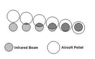
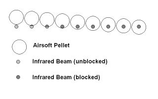
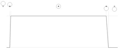
The airsoft pellet counter depends on a photogate to detect a pellet as it leaves the barrel of the gun in order to signal the counter to count down. As the pellet interrupts the infrared beam in the photogate, it sends one clock pulse to the counter. The electronics in the counter have measured values for various properties like rise and fall times or maximum input frequencies. Because of this, a pellet could be traveling too fast through the photogate to be detected, resulting in a miscount. Our goal is to make this product compatible with as many existing airsoft products as possible, so we need to make sure that the pellets will be detected, regardless of the speed or rate at which they are fired. Typical airsoft guns fire pellets in the range from about 300 ft/s (91.4 m/s) to 400 ft/s (121.9 m/s) at about 15 rounds per second, but highly upgraded and modified ones can reach velocities up to 800 ft/s (243.8 m/s) and rates up to 40 rounds per second. The most commonly used pellets in airsoft have a nominal diameter of 6mm, but are actually closer to 5.95mm in diameter. This slight difference in diameter will be neglected.
We are assuming that the beam that is being interrupted was sufficiently small that we could assume that when a pellet was between the LED and phototransistor, it would block the beam, rather than cause only a proportional drop relative to how much of the beam was being blocked. We are also assuming that the potentiometer in the photogate circuit is calibrated such that any decrease in the voltage output of the phototransistor will trigger the switching transistor to initiate a pulse into the counter, but not so sensitive that it will randomly switch due to slight fluctuations in ambient light.
Using the higher velocity range for a typical airsoft gun, the pellet would be traveling at about 120 m/s. This would mean that the beam would be interrupted for 5.0 x 10^-5 s, or 50,000 ns. Based on the specifications of the switching transistor being used, the switching time based on the delay, rise, and fall times should be in the range of about 25 ns to 60ns. This means the transistor should be able to switch from low to high and back to low within 100 ns, 10 MHz. This is sufficiently fast, as the counting circuit, at the voltages being used, 9 Volts, has a maximum input frequency of 8 MHz. So, with the amount of time a pellet traveling at typical speeds, interrupts the beam, the switching transistor should easily be able to create a clean clock pulse that the counter can recognize. At 120 m/s, the interrupt time of 50,000 ns is over 400 times the minimum time needed determined by the counter. Doing the same calculations for a pellet traveling at 300 m/s, which is faster than even the very high end airsoft guns can fire, the interruption time is still 20,000 ns, which is still 160 times the minimum required. Based on the assumptions, we believe the counter, if sufficiently calibrated, should be able to detect the pellets properly, regardless of velocity. With an interrupt time of over 150 times the minimum value, even if the circuit is not perfectly tuned, it should still be able to detect even the fasted airsoft pellets.
Rate of fire must also be considered for detecting the pellets. The calculations of frequency relative to velocity are done under the assumption that immediately after the transistor has switched back to its high voltage state, another pellet is following behind it to interrupt the beam again. For a gun firing at 40 rounds per second, there will be 40 count pulses per second, meaning the pulses will spaced by 0.025 seconds, or 25,000,000 ns. This gives the circuit ample time to switch when it registers a pellet passing through (~30 ns), remain at that state while the pellet remains blocking the beam (~50,000 ns), then return to its original state (~60 ns). So, even at the highest rates of fire for airosft, the photogate should be able to register a correct count.
Design for Manufacture
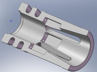
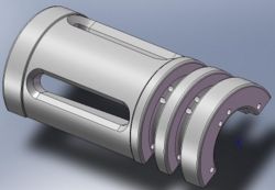
The manufactured parts of our ammunition counter are relatively simple and should not pose any manufacturing issues. For example, our rail clamp clip is an extruded shape with a hole perpendicular to the extrusion. Milling something of that complexity is very straightforward. The one part that may pose a manufacturing issue is the flash hider. The flash hider has a small section cut out of the inner diameter to house the flash hider. Creating the small section may not be possible since neither milling nor a lathe would be able to reach into the small inner diameter and cut out a rectangular area. Our team believes this can be made accessible by making the flash hider into two parts. Each half would be made as though the flash hider had been cut through the diameter of the flash hider's circular profile. The halves could be designed to fit together by a snap fit process.
The other issue with the flash hider is that the small section has two holes in it to allow the photogate sensor to be wired to the display box. There is not enough clearance for the hole to be drilled from either side. One solution for this would be to just drill the holes all the way through from the outside of the flash hider.
Failure Mode Effects Analysis
A good way to improve the design of a product is to analyze different potential failure modes. This chart below analyzes the ways in our ammunition counter could potentially fail.
| Item and Function | Failure Mode | Effects of Failure | S | Causes of Failure | O | Design Controls | D | RPN | Recommended Actions | Responsibility and Deadline | Actions Taken | S | O | D | RPN |
|---|---|---|---|---|---|---|---|---|---|---|---|---|---|---|---|
Display Box
| Bending | Potential damage to electronics | 8 | Excessive stress | 2 | Stress analysis | 3 | 48 | Not likely, so ignore | Display box assembly | - | 8 | 2 | 3 | 48 |
Battery Cover
| Bending | Loss of electrical power | 8 | Excessive stress while back cover is removed from display box | 3 | Stress analysis | 3 | 72 | Not likely, so ignore | Back cover assembly | - | 8 | 3 | 3 | 72 |
Circuit Board
| Short circuit | LED displays will not show the correct ammunition count | 8 | Water enters display box through the wire holes in the back | 7 | Specify wire hole tolerances | 6 | 336 | Re-design. Use headphone jack to carry electrical signal. Wire holes can be dimensioned to have a headphone jack fit snugly into it making it more difficult for water to enter the display box | Circuit board assembly | - | 8 | 7 | 6 | 336 |
| Malfunction | dim LED display, circuit will not count when pellets are fired | 8 | low battery power | 10 | User testing | 8 | 640 | Include a note about low battery power into the user's manual. | Circuit board assembly | - | 8 | 10 | 8 | 640
| |
LED Display Holder
| Bending | Damage to LED display | 8 | Excessive stress | 2 | Stress Analysis | 3 | 48 | Not likely, so ignore | LED display holder assembly | - | 8 | 2 | 3 | 48 |
LED Display
| Poor electrical connection | Numbers will not display correctly | 8 | Stress during assembly | 2 | Quality assurance during assembly | 2 | 32 | Not likely, so ignore | Display box assembly | - | 8 | 2 | 2 | 32 |
Flash Hider
| Bending | Photogate sensor will not detect gun fire, pellets ricochet off flash hider, barrel of user's gun breaks | 8 | Hit against a hard object | 3 | Stress Analysis | 3 | 72 | Not likely, so ignore | Flash hider assembly | - | 8 | 3 | 3 | 72 |
Photogate sensor
| Poor electrical connection | Sensor will not detect gun firing | 8 | Stress during assembly | 3 | Quality assurance during assembly | 2 | 48 | Not likely, so ignore | Flash hider assembly | - | 8 | 3 | 2 | 48 |
Display Box Clamp
| Shearing | Display box will not mount to user's gun | 8 | Excessive stress | 3 | Stress analysis | 3 | 72 | Not likely, so ignore | Display box clamp assembly | - | 8 | 3 | 3 | 72 |
Rail Clamp Clip
| Shearing | Display box will not mount to user's gun | 8 | Excessive stress | 3 | Stress analysis | 3 | 72 | Not likely, so ignore | Rail clamp clip assembly | - | 8 | 3 | 3 | 72 |
Rail Clamp Base
| Bending | Display box will not mount off of a gun's top rail | 7 | Excessive stress | 3 | Stress analysis | 3 | 63 | Not likely, so ignore | Rail clamp base assembly | - | 7 | 3 | 3 | 63 |
The only major issue with our counter right now is with the wire holes in the display box. Since airsoft games are sometimes played in rainy or snowy conditions, it is possible that water will enter the display box through the wire holes at the back. If enough water fills the display box, the electronics inside will short circuit. This problem can be fixed by combining the wires that connect the flash hider and display box into a headphone jack. This jack would be made to fit snugly into the wire hole at the back of the display box much like the audio-out port on computers and MP3 players. The tight fitting between the wire hole and headphone jack would make it more difficult for water to enter the display box.
The other failure mode that scored a high RPN is the low battery power issue. There is no engineering design that can change the fact that batteries will run low on power and that they will eventually have to be replaced. The only thing that can be done is to include a note about changing the batteries when the counter is not functioning properly or when the LED display is dim in the user's manual. If the consumer really feels replacing batteries is a big issue, then the circuit could be redesigned to consume less power.
Overall, the FMEA shows that the only problem areas are those areas relating to electronics. Other failure modes such as bending or shearing are not issues because they were unlikely to occur. The reason for this is that our counter is made mainly from aluminum which is more than strong enough to handle whatever loads our counter will experience.
Quality Function Deployment
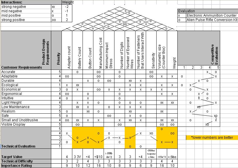
Below is an product planning matrix that compares our design with the Alien Pulse Rifle Conversion Kit, a competing airsoft product with an LED ammunition counter.
From the product planning matrix, we can see that the volumetric size of the counter box and the manufacturing cost are shown to be very important to our final product design. A technical evaluation of our product shows that in both these areas the Electronic Ammunition Counter is superior to that of the Alien Pulse Rifle Conversion Kit. The Electronic Ammunition counter has a more simplistic design than the pulse rifle conversion kit, and as a result, the manufacturing cost of the Electronic Ammunition is significantly less than that of the Alien Pulse Rifle Conversion Kit.
From the competitive evaluation column, we see that we can improve the counter design by adding more realism. Although the Alien Pulse Rifle is not based on a realistic gun, it has a higher realism rating than our counter box as the Alien Pulse Rifle aims the mimic the gun from Aliens. Our ammunition counter on the other hand was meant to be placed on a military simulation gun. As a result, the counter should have been hidden in such a fashion that it resembles an accessory used for military simulations. This is one aspect of our ammunition counter that we should look into at a later time.
The product planning matrix also indicates that we can improve our design by reducing the of buttons that the user interacts with and the number of exposed wires. The competitor's product does not have any exposed wires or preset buttons as these features were integrated into the gun. The addition of exposed wires and preset button cause our counter to look less realistic and less ergonomical. Although our counter has poor ratings in these area when compared with the pulse rifle modification kit, it is a necessary evil as our electronic counter is more adaptable as a result of these trade offs. Our goal was to design an aftermarket product that can be used on nearly any airsoft gun, and to do this, a bit of convenience and realism has to be sacrificed. Whereas the Alien Pulse Rifle Conversion Kit targets players who want a gun based on a movie, the Electronic Ammunition Counter was designed for any airsoft player who wants to know the ammunition count in their magazines.
Possible ways to reduce the number of exposed wires though include adding a transmitter and receiver to the flash hider and counter. This is another area in which we can study at a further point in time.
The Prototype
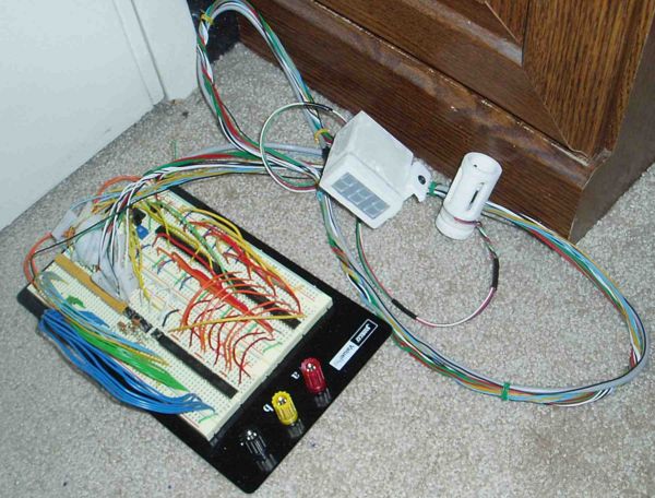
The images above shows our prototype. All parts were printed on the Z-Corp 3D printer. The parts were first modeled with SolidWorks, then saved as stl files. Finally we printed loaded the stl files on the Z-Corp printer and printed our prototype. The prototype was made so as to demonstrates the overall size of the flash hider and the counter box. The prototype also serves to show the location of the preset buttons, reset button, cables, printed circuit board mounts, and photogate locations. Having a 3d model printed was useful since we got better user feedback as a result. Potential customers were able to grasp our design concept faster. Instead of having to focus on how our product might look, potential customers could instead focus on areas that they liked or disliked.
Our prototype is not complete. One way in which our prototype differs from the finished product is in the fact that the prototyped flash hider is not threaded. Due to the limitations of Z Corp printer, even if we had printed the threading, after the coating is applied, the threading dimensions would be rendered useless. Fasteners are not shown either. Ideally we would like to have snap fits to attach the front of the display cover to the electronics box. The 3 volt button cells is secured with a snap-on cover. Our finished product would most likely be made from casted or machined aluminum to give it a more solid feel.
User Testing and Feedback
Our user testing and feedback comes from a veteran airsoft player named Nick who tested our prototype on two of his guns. Nick has been playing in airsoft games for years and owns many airsoft guns and accessories. His friend Kazu, who is so also an airsoft enthusiast, was also present during our prototype testing. Below is a list of positive and negative things that they said about our design:
Positive Feedback:
- "Good job"
- "Tell me when you're done building this, I want to buy one"
- Nick thought our product could be sold for $100
- Nick was laughing when he watched a video replay of the counter in action
Negative Feedback:
- Nick and Kazu agreed they wanted the LED display to be centered over the gun rather than hanging off the side
- Kazu wanted a smaller LED display
- Nick suggested using a holographic display much like EOTech's sights for future products (see the Conclusion and Next Step section)
- Nick thought the wires from the flash hider to the display box were unsightly.
Conclusion and the Next Step
The current prototype is exactly that, a prototype. There really needs to be at least one more redesign before it will be ready to be a marketable product. From the user feedback we got from our prototype, veteran airsoft players thought it was a good idea, but the housing for it was not the ideal solution. One user said it would be incredibly useful since it has not been effectively done before (the M41A modification kit is not an ideal solution). For users who use high capacity magazines ("hi-caps" for short), this would not really be as useful or necessary, as the gun can be shaken and the pellets shake around in the open compartment in those particular magazines. For people who use standard or middle capacity magazines, this would be much more useful since the pellets are held in place and fed into the gun by a compressed spring, rather than being loose in a compartment. There is no way to check how much ammunition you have remaining.
In the future, the design could be switched from the existing design primarily composed of ten integrated circuit (IC) chips down to just one programmable chip. The routing of the wires in the circuit is somewhat complex, especially when trying to fit it into as small a space as possible. Cost could increase depending on how many layers each circuit board is, and more layers might be needed to get the necessary wire routing. Another feature that could be added relatively easily when switching to a programmable chip is the ability to stop at 000 or not display digits if they are a leading 0, for example, just displaying "55" instead of "055". This can be done purely with existing ICs, but it adds extra complexity and circuit board space. Currently, the prototype will loop back to 999 after it reaches 000.
There is a possibility of a product family where the counter box is sold with the photogate built into a flash hider or a mock silencer. The flash hider or silencers could be sold individually with different designs, based on the varying designs of the flash hiders of different models of guns, since different guns have drastically different looking flash hiders. Also, if the electronics are designed properly, there could also be different colored displays. From our searching, the only displays with three digits were red, yellow, or green. These could be made such that the front piece is replaceable with a different colored display, depending on the user's preference. The need for this could be determined based on more user feedback. The variety of colors could be increased also if two- or four-digit displays were able to be used.
Also, if it is researched more, the possibility of putting it in a casing kind of like an EOTech holographic sight, it would be the "coolest" version, especially if the display value could be integrated into the HUD. It would allow for a bit more space which would help the space needed for circuitry as well as a larger capacity battery, like a standard 9V battery, which is cheaper and easier to replace than lithium ion button cell batteries currently used. It would make it very realistic, since the counter would be "camouflaged" in a realistic real steel add-on (which is what airsoft users want).
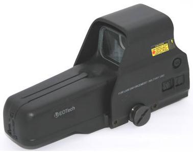
Source: http://www.eotech-inc.com/product.php?id=8&cat=1
The possibility of having the count transmitted by an IR signal, kind of like a TV remote control, or by some sort of radio signal, like an RC car would eliminate the need for a wire connecting the flash hider or mock silencer, but it would only be possible with a mock silencer, since the front part would need to have its own power supply.
The final improvement our product could use is to have a magazine automatically tell the counter how much ammunition is in it rather than relying on the user to enter that number. This could be accomplished through custom magazines for the most popular families of airsoft guns such as the M4, P90, G36, etc. This goes back to one of our earlier ideas with the counter being in the magazine. The downside to this would be that it would add an extra component into the gun, and therefore an extra unhidden wire. If internal modification was "allowable" then more could be hidden, but we are aiming to have it not require any disassembly of any gun to work. The alternative is that a transmitter could be used in place of a wire and so it would not have the problem of unsightly wires.
The Design Process and the Design Team
It all began when we decided to form a team for our engineering design project. We were friends and knew each other from other engineering classes. We wanted our project to be something that we found interesting. Since Charles and Luke were interested in airsoft guns and modifications, we started our project with the intent of redesigning an airsoft gun. Charles then used our budget to order an L96. In our first report, we examined the inner workings of a disassembled L96 and discussed the market for airsoft guns. The next step in the project was to think of ideas for redesign of the L96. Our team meet outside of class and even used online collaboration software to brainstorm new ideas. In fact, we even attended an airsoft tournament to help us generate ideas for a redesign. We came up with five great ideas for a redesign, but ultimately we chose the ammunition counter idea since it had never been done before for airsoft guns. We came up with many different ways to designing an ammunition counter but after presenting these ideas to the class, we knew we had to go back to the drawing board. One day after a class of Engineering Analysis, Charles and Luke came up with the initial idea for our prototype by drawing conceptual ideas on paper. With this insight, Charles worked on the electronics, Terry made CAD models, and Luke took care of documentation. Following a late night session of CAD modeling by all of us, we had a fully complete CAD model of all our prototype parts. The day after Terry and Luke printed our CAD models on the Z-Corp printer in the machine shop. Since some of our printed parts broke or had design flaws in them due to the tolerances of the printer, Charles and Luke reprinted our models on the Z-corp printer the next day. The only thing missing at this point in time was the electronics. Through long hours of debugging, Charles completed the fully functional circuit. With that, he finalized our prototype by assembling it with super glue.
Terry Chau
- Designed CAD models of the L96 and clamps
- Printed prototype parts on the Z-Corp printer
- Contributed greatly on written reports
- Attended an airsoft event
- Attended weekly out-of-class meetings
- Created a PowerPoint slide show for the final presentation
- Presented prototype ideas to the engineering design class
Luke Miller
- Designed the CAD models for the display box, battery cover, display piece
- Spawned ideas for the final prototype
- Printed prototype parts on the Z-Corp printer twice
- Contributed greatly on written reports
- Attended an airsoft event
- Attended weekly out-of-class meetings
- Presented design ideas to the engineering design class
Charles Yee
- Completed the counter's electronics
- Ordered the L96 and electronics
- Printed prototype parts on the Z-Corp printer
- Designed the CAD model for the flash hider
- Spawned ideas for the final prototype
- Assembled the final prototype
- Attended an airsoft event
- Attended weekly out-of-class meetings
