Automatic can opener redesign
From DDL Wiki
Executive Summary
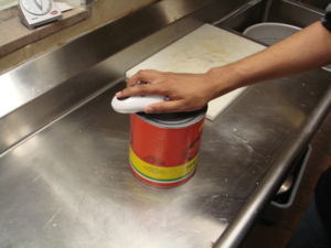
The OneTouch Automatic can opener gives users a convenient and simpler way to open cans as compared to the usual manual types of can openers. The purpose of this page is to analyze the current design aspects of the can opener and to see what improvements could possibly be made. Even though we could have our own ideas as to what is important to users when using the can opener, we had to conduct research by way of a survey to see exactly what the user was looking for in regards to an automatic can opener. The two main aspects of the can opener that were most important to the user were safety and ease of use. After analyzing the can opener thoroughly we decided as a team to focus on the ease of use aspect. When looking at the can opener’s safety aspects we thought the original design was very safe and that there really was not much that we could do to increase the safety.
With ease of use as our number one objective in the redesign of the can opener we had to then specify exactly what we could improve to achieve this objective. The first thing that we discussed was the ergonomics of the original can opener. We felt that the original can opener was somewhat bulky and could be designed to fit in the hands of the user better, but the cost of the can opener was very reasonable so we did not want to have to increase that. This led to a few specific design changes that we felt would benefit the user. The specifics of these changes can be read in detail in the text below.
With our new design we feel that the consumer will react very positively to the changes that we have made since they follow exactly what the consumer was looking for in the survey. Below we will discuss in detail the new design aspects and the analysis that was conducted which was the basis of our changes.
Background Information
The original can opener has many quality features that made it hard for us to decide exactly what to change. The safety features were probably the best aspects that we saw on the can opener. Some of the safety features that were on the can opener already included a safety switch and a well covered blade. The safety switch made it so that the user could only turn on the can opener when it was sitting on top of the can. This prevents children from finding the can opener and cutting their fingers. The well covered blade gives a very solid barrier between your fingers and the blade when operating the can opener. Another safety feature was the way that the can opener actually opened the can. It cut on the outer edge of the can just below the lip so that it did not leave any sharp jagged edges behind. One of the problems that we saw in the origianl design was the location and design of the manual override. To us it seemed that this aspect of the original can opener took a lot away from the ease of use for the customer. The original can opener’s outer design also appeared to be somewhat bulky to us which took away from the ergonomics of the can opener.
Market Research
Market research is a way to allow us to gain knowledge about the target consumers. Therefore we have completed a survey and obtain a sample size of 107. Three questions were asked in the survey and they are:
- "What is the most significant feature"
- "What is the most problematic"
- "What is the most significant changes that applies to an automatic can opener".
Based on the results of the survey, we generated five ideas that we believe we would pursue on.The ideas are:
- the LED status light,
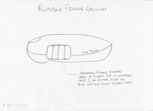
- Finger grooves to increase comfort,
- Silion casting for water proofing,
- Using triple AAA batteries to diminish size
- an manual override for ease of use.
Survey graphs
Please rank how important are the following features to you when you buy a can opener?
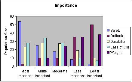
From this graph, it showed that safety is definitely the most important concern that consumers have. Ease of Use came second, Durability came third, Weight came fourth and the Outook (size, Style of the can opener seemed to be the least significant feature among all.
Please rank which aspect you think is the most problematic with can openers?
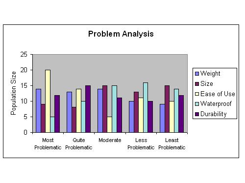
Apparently, ease of use is the most concerned problem. Then it comes to waterproofing, where it tends to be troublesome for users either when their hands were wet or when the can opener was dropped into water and had malfunctionability. Weight is the next concern, where girl users or higher aged group consumers believe the current designs of can openers are a little too bulky and heavy. Durability came next. Most of the consumers tend to still use original hand driven can openers, and they were concerned about the rusting and how the blades will get dulled. Size is the least concern as most of them believed the current size was ideal.
Please rank the following new features that you felt is most significant for an electric can opener?
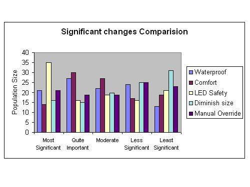
Not surprising that since safety was the highest importance in the consumers mind, the LED satefy feature was the most significant in consumers' minds. Waterproofing came in second , so it justified that there is a need to improve when the can opener is involved with water. Thirdly, is the option for a manual override. Reason believed is that an automatic can opener would not be able to function properly if it faced a notch dent. Lastly, Comfort and Sizes are good improvements that the consumers believed that would have a significant impact
Market Research conclusions
Due to the nature of our environment, the majority of our sample are college students. We believe that our can openers' target consumers' age is wide ranged,from young kids to elderlys. Therefore our sample results might not accurately reflect the total population. Different outcomes and deviations between our sample results and the truth could occur. An example would be that even though weight was not a big issue for our sample population, but in reality elderlys would prioritize it much higher among the list. Overall from our survey, we can tell that safety is the highest priority, which is also reflected by the high rank of the LED status changes. Ease of use is also another significant aspect that affects durability and a high concern among the users. In general, the results from the market research supported our thoughts in what aspects that concerns the users and justifies the need for improvement. With the newly changes that will be made to the automatic can opener will be a much better product itself.
Value Oportunity Analysis
In our VOA we decided to look at the aspects of our automatic can opener that we thought had the most room for improvement. We decided that we would rather have a product that was better in more categories than extraordinary in a couple. This would lead to a better product overall. Our results can be viewed in the Automatic Can Opener VOA chart.
Our new ideas for imrovement help with most aspects of the can opener that we felt were on the low end of the VOA chart. Since our idea for improvement has different components we are able to please more people because of the number of positive changes to the can opener. Our main focus was on the ergonomics of the can opener. Our prospective changes to the product improve every aspect of ergonomics on the chart: comfort, safety and ease of use. A combination of the LED lights, rubber grips, water-proofing and changes in the battery source and manual override are the prospective changes that we are looking at the most. So, compared to the present can opener our new ideas for improvement lead to a better product.
Sketches
- Current Design:
- No comfortable grip
- Slippery if wet
- New Design:
- Finger Grooves
- No-Slip rubber
The current design involves no comfortable way for the user to grip the can opener. It is bulky and hard for a user with small hands to grip completely. This problem is exacerbated if the users hands or the opener itself is moist. To overcome such problems, our first proposed design entails the addition of finger grooves contoured to an average sized hand which will afford the user the opportunity to completely and comfortably grip the can opener. These grooves would be added to either side of the can opener so as to accommodate both left and right handed users. To attack the problem of "slippery when wet" we intend to add some type of non slip surface. This could either be done by adding a vulcanized rubber or a spray on silicone. It would be added to each half separately so as not to impede the opening of the casing to access the battery terminals.
- Current Override:
- Impractical
- Hard To Reach
- New Design:
- Ergonomic
- Easy to Use
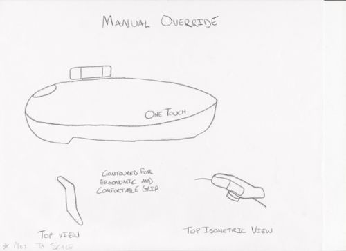
The original can opener has a manual override that is located on the underside of the opener near the blade and the cutting wheel. This location is impractical and reach, especially if it is in mid-cycle. A screwdriver is also required to utilized this manual override and often the entire apparatus must be turned upside down unless a perfect position on the edge of a table can be achieved. These inconveniences can be overcome with the addition of a manual override that is similar to an ordinary manual can opener. The new override will also be contoured in such a way that a wide variety of demographics will be able to use it comfortably.
- Current Design:
- Hesitation during Cycle
- Mechanism status is unclear
- New Design:
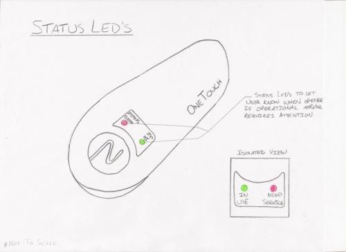
- Red & Green LED’s to indicate functional status
A problem that has been experienced with the original can opener is hesitation during a cycle or hangups on dents. This can cause confusion for the user as they may not know that there can is not open because a full cycle was not completed. To overcome this we proposed the idea of instating LED Status lights. A green light would indicate that the opener is functioning correctly. A red light would indicate that the opener has not completed its cycle and requires attention from the user.
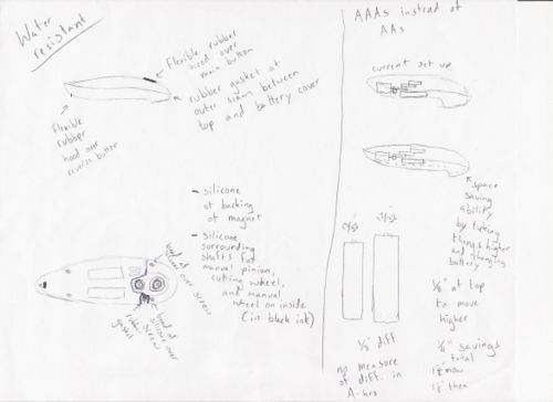
The above image refers to two design concepts: 1. Waterproofing the Can Opener; 2: Switching from AA to AAA Batteries
- Current Design (Waterproofing):
- No seal over blade or battery compartment
- No seal over buttons
- New Design:
- Rubber Gasket
- Rubber Hoods
- Silicone
The design of the current can opener does not include any form of waterproofing to protect the internal components from wetness. If the user were to spill the contents of the can being opened or if they were to drop the opener into the sink, there is a chance that the can opener would be ruined. To tackle this problem we propose to insert a rubber gasket between the upper and lower shells. It would be attached to the shell so that it would not have to be placed properly every time the batteries need changing. A drop of silicone gel would be placed over the screws, magnet, and cutting wheel. Rubber gasket hoods would also be place over the Activation button and the reverse button.
- Current Design (Batteries):
- AA Batteries
- Bulky
- New Design:
- AAA Batteries
- Smaller and Space Saving
Engineering Analysis
Analysis Overview
In order to implement changes to the current design and to build a prototype of our proposed design, we first needed to understand how the components of the original can opener operated. The first step to this was to analyze gear ratios throughout the entire opener. Those numbers are listed below. Forces exerted by the opener were also analyzed and it was determined that the a force of 25 lb. was needed to pierce the can and a sideways cutting force of 15 lb. was need to continue opening the can after it was pierced.
The largest change implemented upon our can opener was the replacement of the old motor, with a newer and faster motor. A comparison of the two motors is as follows: the old motor operated at 15847 rpm with no load while the new motor operates at 23161 rpm (an increase of 46%) under the same conditions; the no load speed for one revolution with the old motor was 25.4 seconds and the new motor reduced this time by 32% to 17.2 seconds; the old motor movement wheel speed was 13 rpm (with a movement wheel diameter of .5 inches) with no load and this figure was increased nearly 50% to 19 rpm with the new motor. We also removed one gear from our gear train which increased the movement wheel speed to 97.2 rpm (an increase of over 500%). This turned out to be unsafe as the opener would spin off the can while the blade was still engaged.
We set a goal for our new design of being able to remove the top of a test can (with a diameter of 2.75 inches and a circumference of 8.64 inches) in 20 seconds. The motor speed necessary for this would be just over 20000 rpm and the movement wheel would need to rotate 16.5 rpm or .432 in/s.
Other design changes included a new manual override and an LED light system. The cutting torque necessary to use the manual override is 1.42 lb-in. With a new moment arm of 1 inch, the user need only exert a force of 1.42 lb to utilize the manual override. The LED circuit would entail being wired in parallel to the motor. Two standard diodes would be wired in series with a Green LED that contributes a voltage drop of around 2 Volts in order to make the appropriate circuit.
Testing Procedures
A large portion of the data for the analysis work came from testing both the original product as well as the final prototype. Other testing on intermediate prototypes also provided some information. Most of the remaining data is all in the form of dimensions collected through measurements of gear sizes. Main tests were used to find the amount of torque and speed the original motor had, the actual amount of torque and speed that the new motor had, as well as the required forces to pierce and cut the can. Other tests to compare the new and old openers were conducted between the original opener and prototype running on cans. The main point was to see the loaded cycle times in order to see how much time was saved by the extra torque of the new motor. The loaded cycle times were 23 seconds for the new motor and 32 seconds for the original motor. A final test was conducted to compare the AA versus AAA batteries. Although the AAA batteries opened only around 63% of the cans opened with AA batteries, we feel that this statistic would change for the better if the ideal motor was found because it would operate at better efficiency.
To find the amount of torque that both the new and old motors employed, the same test was used to ensure comparability. Because the cutting wheel operates on a crank we were able to use a force gauge to find out the stall torque by finding the required amount of force required to stop the cutting wheel from operating on its crank. Both motors had an extremely high stall torque at the cutting wheel in comparison to the actual force necessary. The new motor still maintained a higher stall torque by roughly 25 %. To test for the speed of each of the motors while they were unloaded a very simply test was used, although it also decreases the accuracy of the test. By watching and timing the number of revolutions of the movement wheel and calculating back through the gear ratios, we were able to get an idea of the speeds of each of the openers.
In a similar manner, experiments were set up to be able to find the required piercing and cutting forces. To find the piercing forces required, a can was placed sideways in a vice initially. Using a slide set up to hold the blade as to insure a proper entry direction, a force gauge was used to see the required force for the blade to pierce the wall of the can. To find the sideways cutting force, the can was removed from the vice and a bolt was put into the top at a distance of 1in from the center. With the blade in position to cut the can, once again a force gauge was used to see how much force was required to spin the can using the bolt in order to cut the can.
Analysis Data
- Force Necessary to pierce can 25lb
- Sideways cutting force 15lb
- Movement wheel .5in dia
- Blade on a .598in crank
- Ratio between movement and cutting gear
1. During piercing – 1:2.7
2.During movement – 1:4.7
- Gear ratios
1. Pinion to 1st – 1:6
2. 1st to 2nd – 1:5.11
3. 1st to 3rd – 1:5.68
4. 2nd to 3rd – 1:5.68
5. 3rd to movement – 1:7
6. Overall to movement – 1:1219
7. Overall to cutting ( piercing) – 1:3291
8. Overall to cutting ( moving) – 1:5729.3
- Ratio between manual override and movement gear
1. 1:5.25
- Piercing torque w/ manual override
1. 1.05 lb-in
- Cutting Torque Necessary w/ manual override
1. 1.42lb-in
- Manual Override new moment arm – 1in
- Force input to manual override – 1.42lb
- No load old motor @ movement wheel 13rpm or .22rps
- No load new motor @ movement wheel 19rpm or .32rps
- 1 revolution moves 1.57in around can
- Old motor – 20.41in /min or .34in/s
- New motor – 29.83in/min or .50in/s
- Test can diameter 2.75in
- Test can circumference 8.64in
- Old motor no load cut 25.4s
- New motor no load cut 17.2s
- No load old motor speed – 15847rpm
- No load new motor speed – 23161rpm
- Overall Gear ratio w/ 1 less gear @ movement 238.56
1. 1.61rps new motor
2. 2.53in/s
3. 3.42s
- Cut time goal 20s
1. 0.432in/s
2. 0.275rps or 16.5rpm @ movement wheel
3. Motor speed goal 20113.5rpm
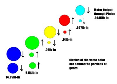
- Piercing torque necessary – 14.95lb-in
1. Motor needs - .0045lb-in
- Movement torque necessary – 7.5 lb-in
1. Motor needs - .0013lb-in
- Ideal motor specs @ max efficiency
1. 20000rpm and .0135lb-in for factor of safety of 3
- LED circuit
1. Parallel to motor
2. LED in series with two standard diodes
3. Preferably green LED = V drop ~ 2.0 V
- Battery Length Testing
1. Loaded Old Opener = 83 Cans
2. Loaded New Opener = 51 Cans
Here is also a free body diagram of the required forces through the system.
Pugh Chart
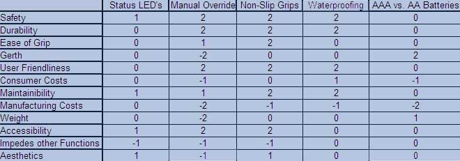
- This Pugh Chart is a representation of how each design innovation will effect certain aspects of the overall quality of the Automatic Can Opener. The most important aspect to the consumer is at the top of the left hand column. Each row from the top becomes successively less important to the consumer. The rankings are based in part on formal market research (obtained from our survey) and informal talks with people who used the product.
Quality Function Deployment
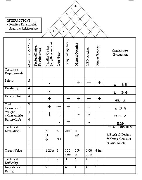
Based on our assessment, compared with the competition we are either above or in the same category in terms of safety, durability, ease of use and weight. Currently even though we have a slight disadvantage in the battery life and cost of our product with the competition, the difference was not significant enough to make a significant impact to the consumers. We believe our target consumers' age will be wide ranged from young adults to high elderlys.
Detailed Design Description
In regards to the survey results, the ease of use aspect led us to our first few design changes. In regards to the bulkiness we wanted to make the can opener smaller and more streamlined, so we had to think of ways to make space. The first idea we had was to use AAA batteries instead of AA. This proved to work the best and it also saved us some much needed space. In dealing with ergonomics we felt that adding finger grooves and a sticky surface to the exterior of the can opener would help with the comfort of holding the can opener. The original design was very smooth so it would be hard to hold if your hands were not exactly dry. The changes would also help with the safety of the product because the user would be less likely to drop the can opener. Another improvement with the casing that we decided to do is making snap fit pieces so that we could eliminate a lot of fasteners in the assembly of the exterior. This would cut out a lot of time needed to assemble the product and would end up saving the company a lot of money. The next change that we made on the original was the location and design of the manual override. In the original the manual override is very inconveniently placed on the bottom of the can opener and a wrench is needed to use it. With our new design we put the manual override on the top and will have it resembling a normal manual can opener. This will give the user an easier way to manually open the can if the can opener fails. The next aspect involving ease of use was the runtime for one cycle. We wanted to decrease this so that the user did not have to wait as long to open a can. The elimination of gears would also have helped this idea but in our second prototype it proved to go too fast. The next idea we had was installing a new motor with the original gear train. This proved to be the best choice because the new motor cut down cycle time from 33 seconds to 24 seconds, which is not too fast that we have to worry about safety. Even though the safety features of the original design are very solid we still wanted to try and improve some aspect of the safety in our new design. We decided to put something on the can opener that could be used to indicate that something was wrong with the interior. This would make it easier for the user to tell if there was a problem with the can opener as opposed to just dead batteries. We decided to go with an LED that could tell the user if the can opener is operating or not. With these added design features we feel that our can opener is superior to the original, and we can produce this can opener at the same cost or even lower.
Components
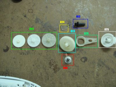
The can opener has several components and electrical assemblies. It appears that most are purchased from suppliers while casings are injection molded in house. Some components seem like they could be removed to allow for a faster and easier assembly. Also, with a large enough scale of production, it may be beneficial to begin making some of the injection molded gears in house as well. Much more detail as to what individual components are used, what their purpose is, and their likely manufacturing processes.
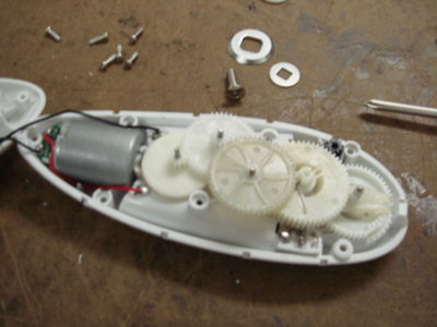
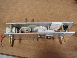
The geartrain is very compact although it does allow for a large conversion from motor speed to torque allowing for an easily made cut.
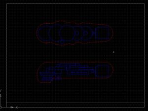
To figure out a reasonable size for the new shells that will include finger grooves and quick snap connectors, the parts were drawn in CAD so that dimensions would be correct. From there, a rough shape was fitted to encase the internal components.
Assembling the new can opener is very similar to the old. Starting with the lower casing, pressure switches and battery terminals are put into place and soldered to their respective wires. Axles and gears are slid into place and then the movement wheel and cutting wheel are attached from underneath. The motor is then placed in and soldered to its connections. At the same time, the top shell can be fitted with the main button and the few switches, as well as the new LED and diodes. All of the electrical connections can then be soldered. At this point the top and bottom shells can be attached with the built in quick connections to finish enclosing the internal components. Beyond this, the battery casing must be slid on and the opener is complete.
DFMA Analysis
Design for Manufacturing:
- Plastic gears and components are injection molded in mass production, which would be more cost effective.
- Movement wheel and the washers are both stamped
- Overall, the whole manufacturing process is very cost effective and most of them are produced by molding and stamping.
In general, the DFM is well developed but has room for improvement. As many parts are outsourced, such as the gears, the manufacturing does not require much design for them. However if they produce their own mold, they would be able to reduce cycle time in the long run. If we have all necessary fillets and chamfers to make extraction of parts easier. These components could be redesigned to improve design for assembly too.
Possible Improvements
- Produce components in bulk to be cost effective
- Produce molds and injection molding in house, which would reduce cycle time.
Design for Assembly:
- Quick Snaps would eliminate the screws and easier for alignement
- Better Alignment would lead to less error in aligning the components within the casing
- The Circuit board and the capacitors are soldered in so it will be secured and hard to disassembly.
- Gear Trains and the movement gear are all secured by shafts
Design for Disassembly:
- Easy dissemble for most parts as most of them are attached by quick snaps
- The more difficult areas would be the motor itself and the circuit board (soldered in)
In general, the DFA is well optimized but has room for improvement. By incorporation of quick snap clips into the design of the casing components, it would be possible to decrease assembly time by not having to screw in seven fasteners to attach the upper and bottom casings. The use of encasing components makes actual placement of parts easy since it all goes from one base mainly. This also makes it so individual gears do no need to be pinned into place for the most part as well as the motor is held in place only by the casing pieces. Another opportunity could be a snap together joint for the movement gear and wheel rather than the method of pinning used currently.
Possible Improvements
- Quick Snaps would eliminate the screws and easier for alignement
- Encasing components makes actual placement of parts easy since it all goes from one base mainly
- Snap together joint for the movement gear and wheel rather than the method of pinning
Design for Environment
- The components made of plastic could be made from less harmful material, such as making thinner gears to use less of the plastic.
- Aside from design, manufacturing processes can be looked into to try and use less energy, such as using a plastic that requires less energy to heat for injection molding.
- Recycling of material would be ideal. Company collects return damaged products from customers, so it could recycle parts.
The use of less material is definitely a place for improvement as well as trying to use less energy in the manufacturing by doing things like regulating heat more in the process of injection molding or requiring less power for an assembly plant in general. At the same time, we have to make sure that a reduction of material would not lead to an increase of failure in terms of safety and product performance. In terms of the recycle process, the cost will increase and it would cause our product to lose ground in terms of pricing. Therefore it might not be ideal, but its definitely an area that we can explore into.
Opportunities for Improvement
- Many parts, like the gears, were ordered from suppliers but could be made in house, even though that would mean a larger cost at the beginning, it would be worth it in the long run.
- The motor offers speed but not much torque itself, which is one of the reasons why we require many gears in the gear train, so one thought is to provide a higher voltage so that there would be a higher torque.
- There are way too many screws attaching the lower case and upper case, many could be eliminated if the the design of the casing changes to include quick snap connectors.
- The switches and the reset button are exposed to the air, so if by accident the can opener is dropped into water, it could short circuit it. Because of this rubber gaskets and hoods could be used to make the device water-resistant.
- The use of less material and energy in the manufacturing process would improve how environmentally friendly the device is.
The decision to change the overall gear ratio can only be made with proper specifications for the motor telling the torque output. Knowing that we wanted to reach the closest to the equilibrium between motor power input and torque. However without this information it is not possible to see if less torque and more speed would be a viable possibility. A different motor may provide more torque outright, but with size constraints it appears that trying to overpower the voltage a small amount for a little extra power is the only feasible option.
Failure Modes and Effective Analysis
Although there are many causes of failure, there are three failures that stand out for being the worst. Electrically short circuiting would make the device inoperable, which we see as a possibility because of accidentally dropping the unit into water. Another failure would be in the geartrain which would cause a loss of power transfer and the motor relies on a mechanical switch to decide when it turns off. This means that the motor would keep running but the opener would no longer cut further. In terms of casing, quick snaps would be ideal, as it could minimize the failure impact of screws. A safety problem that we also see high is switch malfunctioning because it would cause unintended use. For most of the components, many could be improved by strengthening the soldering connections and use of stronger material.
| Part Number | Part Name | Failure Mode | Effects of Failure | S | Causes of Failure | O | Design Controls | D | RPN | Recommendation |
|---|---|---|---|---|---|---|---|---|---|---|
| 001 | Screws(large) | * A screw that is detached from the casings and the blade | That would lead the casings to fall apart and not attached | 4 | Due to rotting or overstress | 2 | Manual | 2 | 30 | Quick Snaps will eliminate this component
|
| 002 | Pressure switch | * It cannot not detect whether the battery case or the opener is in place | That would be dangerous and one of the safety features will be lost | 6 | Overuse and the connection between those components are loose due to deformation | 4 | Manual | 2 | 14 | Make the openings around them larger for easy recognition and resets easier |
| 003 | Movement Wheel | * Cannot provide the necessary pressure to the cutting wheel to pierce can | That would make the automatic can unworkable | 7 | That may due to overuse and deformation if the opener was hit or environmental influences | 2 | Material | 3 | 36 | Stronger material and coating. |
| 004 | Cap Screw | * Cannot attach the cutting wheel to gearing | That would lead make the cutting wheel not work as the gears would not be able to provide the torque required | 4 | Due to rotting or overstress | 2 | Manual | 2 | 36 | Stronger material and coating. |
| 005 | Cutting Wheel | * Cannot cut through can to remove lid | That would make the whole can opener lose its function | 8 | Due to overuse, material corrosion | 4 | Material and Manual evaluation | 4 | 12 | Stronger material and coating. |
| 006 | Magnet | * Cannot keep the top off from submersing into the can when it is cut off | That would lead the can top to fall into the can | 2 | Losing its polarity due to environment | 2 | Manual evaluation | 3 | 11 | Use of a stronger material that leads to stronger magnetic polarity |
| 007 | Reverse Switch | * It does not reverses the direction of the motor | That would lead the cutting procedure to fail | 6 | Error from the circuit board and short circuit | 2 | Manual calculation and evaluation | 3 | 12 | Add stronger solder to form stronger connections |
| 008 | Manual Pinion | * It does not allows manual rotation of the gear system | Lost the manual dimension control | 7 | Overuse and led to a lack of sensitivity | 3 | Manual calculation and evaulation | 3 | 10 | Use stronger material |
| 009 | Positive Terminal and Negative Terminal | * No power is transmitted | The automatic opener will not have any power | 4 | The connection might be off due to deformation and solder misplacement | 3 | Manual evaluation | 4 | 15 | Add stronger solder to form stronger connections |
| 010 | Main button | * No power is transmitted | The automatic opener will not start | 4 | The connection might be off due to running out of solder | 3 | Manual evaluation | 4 | 15 | Add stronger solder to form stronger connections |
| 011 | Internal Switch | * No circuit so there will be no power | The circuit will not be complete | 6 | The connection might be off due to deformation | 2 | Manual evaluation | 5 | 17 | Make tighter connections |
| 012 | Motor | * Cannot drives geartrain, movement wheel, and cutting wheel | The motor is the element to provide speed and connection to the gears | 8 | Overuse, overheat | 4 | Material, Manual evaluation | 6 | 12 | Add solder to maintain good connections. |
| 013 | Ratio Gears | * Unable to gear down motor output | The whole can will be inoperative | 8 | Overuse, deformation | 3 | Material, Manual evaluation | 4 | 24 | Stronger injection molding, use stronger plastic |
| 014 | Shafts | * Unable to sustain the gear train to usable speed and torque | The whole can will be inoperative | 6 | Overuse, deformation | 3 | Material, Manual evaluation | 5 | 36 | Increase diameter |
| 015 | Blade | * Unable to provide an efficient and continued cut | The whole can will be inoperative | 6 | Overuse, Shearing. Fatigue. Thermal. Wearing | 3 | Material, Manual evaluation | 5 | 36 | Stronger material and thicker blades to increase lifetime |
Final Prototype/Final Design
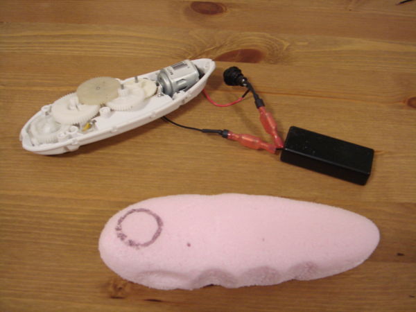
After testing our second prototype we came to the conclusion that the original gear train setup was the optimal choice. In our final prototype we stuck with the original gear ratio and added the new faster motor. This gave us the kind of results that we were looking for. We also switched the power supply from AA batteries to AAA batteries. We did this because we figured that it would be safer for the environment if we switched to a smaller battery. This also gave us some much needed space to incorporate a smaller casing with finger grooves. The finger grooves were modeled on the foam cut out displaying how it would benefit the user by giving them a surer grip on the can opener. From this prototype we learned that faster and smaller is not always better because we were not getting the same battery life with the new motor. This is why in our final design we decided to stick with the AAA batteries but we decided to pick a motor that had specs in between the original motor and our final prototype motor. This will give a longer battery life and should still operate at a faster pace than the original can opener. In our final design we are also adding a few features that we originally planned on incorporating into our prototypes. The first feature is the manual override. This feature allows users to manually open the can if the can opener fails. It will be placed on the top of the can opener so that is easily accessible to the user. The next feature that we will be adding is the LED indicator. This LED indicator will show that the can opener is working. It will help users distinguish between a battery problem or a mechanical problem. Along with the finger grooves in the final prototype we want to add a spary on rubber surface that will give an even better grip than the finger grooves alone. The last thing that our new design will have is the snap fit casing. This will benefit us more on the production side because it will cut down assembly time extremely by taking out all of the fasteners on the casing.
User Testing
Shape Testing
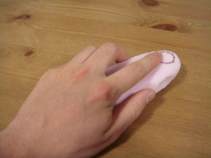
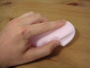
To test the shape of the can opener to go along with the finger grooves and change in interior arrangement, we constructed foam models of possible shapes so that we could ask possible users for their opinion. The two models that we surveyed users on were quite different in size so that we could see what people liked. The first picture shows the model of a longer, narrower model that ended up being liked more by users in the study. This was suprising because we had a biased test study of all men who tend to have larger hands. We would ask about how the shapes felt and what they would like to see changed to make it better. The second picture is of a shorter, wider model which was expected to be liked more by our test group, but turned out to not be liked much at all.
Speed Testing
Our speed testing as a user study was conducted using several different choices of openers. One standard hand crank opener was used so that people could see how much quicker and easier the automatic opener is in comparison. From there, three choices were also used. One was the original model of the opener as we began the study with. The second was our original prototype that was not geared down as much allowing the opener to be much too fast. A third was the final prtotype that is theoretically faster than we were looking for, although loaded in use, the opener was still a little slower than our goal. Users liked the final prototype because of its improvement of around 10 seconds over the time of the original opener. At the same time, users enjoyed the first prototype because of its comical use because of how fast it was. Because of this we understood that the messes it created and uncertainty in falling off made the speed much too fast for a feasible opener. Because of this, our study led us to believe that the final prototype was an improvement over the original because it had a speed more appreciated by end-users.
Conclusion
In regards to this final design being pursued for production we feel that our product is something that people would want to have in their kitchen. As seen above in the QFD analysis we believe that our can opener overall exceeds every other automatic can opener on the market. No other opener offers users the same ease of use as ours and by our survey results we can conclude that this is very important to the user. We were able to factor in this ease of use concept without having to sacrifice any safety features. If anything, we were able to make the can opener safer for users with the installation of the LED indicators. With the decrease in material in the casing the company will end up saving money on raw material used, so even with the new features the can opener should be right around the same price as the original. So again we feel that this design should most definitely be used in production as soon as possible.
Next Steps
So now that our design is being pushed forward in the production process we must identify the next steps that have to be made to make our design a reality. The first thing that we need to do is make sure that the specs of our new casing fit the ideal dimensions of the type of hand that we want to model it after. Since we are not able to do this we will have to send it to a specialist that will take a look at our design and give us the proper dimensions that we are looking for. This is the first barrier that we will come across. Since we are going to have to wait for someone else we want this to be the first thing that we do just so that we are not waiting for someone else before we can go forward with the production. Since things do not always run smoothly we have to have other things that we could do when we are waiting for the industrial engineer to give us the specs for our casing. As we are waiting to hear back, we will be able to test and fine tune our motor with our gear assembly to make sure that the new motor that we speced out will do exactly what we want it to do. Once we get the specs from the industrial engineer we can produce our first prototype with all of the new features that our final design has. Once we have tested the new prototype we will be able to mass produce the final design. We will have to create all new molds and dies to produce our new product. Once these processes have been tested we will be ready to fully produce our new can opener and allow the public to use it after we conduct some user testing research in very specific areas. Once these few select test areas accept our new design we will be ready to mass produce our can opener and distribute it all across the country.
