Door damper
From DDL Wiki
Contents |
Executive Summary
A door damper is a standard piece of industrial hardware that is used on thousands of doors across America. Our team is analyzing competitor door dampers to determine the function, strengths, and weaknesses.
The competitor's damper was dissected in order to gain a better understanding of its functionality and the parts that are used. Following dissection DFM, FMEA, and DFE analyses was performed. DFM analysis revealed that while the parts are mass produced, they are neither standardized nor easy to assemble. FMEA revealed that failures of the product are not only highly unlikely and but also. unlikely to harm the user. Instead, failure modes focused around the door damper becoming unable to fulfill its purpose. DFE analysis revealed that while there was a low carbon dioxide tax cost associated with the manufacturing of the damper, the hydraulic fluid used could be an environmental hazard if disposed of improperly. The lack of disposal instructions or advice implies that proper disposal is unlikely, if possible at all.
We have determined that there are several possible areas of improvement. These improvements are focused around the elimination of the petroleum-based damping fluid, standardization of parts, and the possible addition of features.
Primary Stakeholders and Product Needs
The main stakeholders for this product are the building owners who must absorb the cost of the original door damper and installation, as well as maintenance costs and replacement. Installers (construction workers), maintenance workers, and building planners must also be considered as consumers. In addition the needs of retailers, manufacturers, and transporters must be taken into consideration throughout the design as well. The considerations for each of these stakeholders are summarized in the table below.
| Stakeholder | Needs |
|---|---|
| Consumer |
|
| Retailers |
|
| Manufacturers |
|
| Shipping/Transport |
|
Product Function and Evaluation
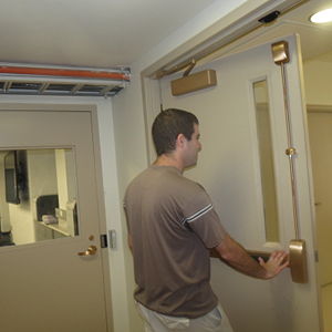
The door damper has two main roles. First, the damper closes the door automatically. Secondly, the damper ensures that the door moves at a safe and controlled rate.
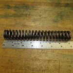
Self closing functionality is achieved with the use of a spring. The spring is compressed as the door is opened. It then expands and forces the door into a closed position.
Speed is controlled by moving a piston through a viscous fluid. Speed can be controlled by opening additional channels to allow the fluid less head loss.
Motion is controlled and transmitted through the use of a two bar linkage, a rack, and a pinion. This provides both mechanical advantage for the spring, as well as allowing the use of a linear spring to cause rotational motion of the door.
Steps for use
- Install door closer to door and frame
- Adjust to desired angle and closing speed
- Push/pull door open
- Allow door to close behind you
A Closer Look at the Damping System
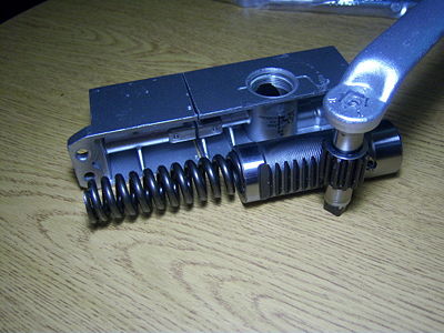
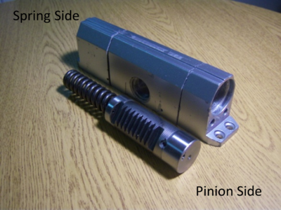
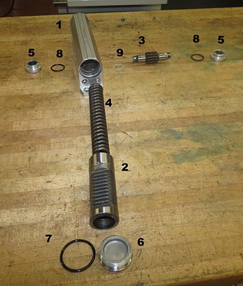
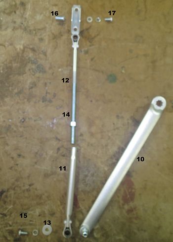
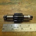
While the linkage system connecting the door damper housing to the door is relatively simple, what occurs inside the damper is much more complex. The swinging motion of the door turns the linkage. The linkage is connected to a pin which in turn transmits rotation through a rack and pinion system. Figure 1 shows how all the components are connected; from the linkage through the pin, through the pinion, through the rack, and to the spring. When someone opens the door, the system compresses the spring. Upon release, the spring exerts a force on the rack and pinion, resulting in the door closing on its own.
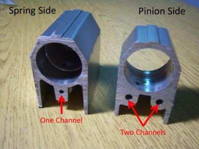
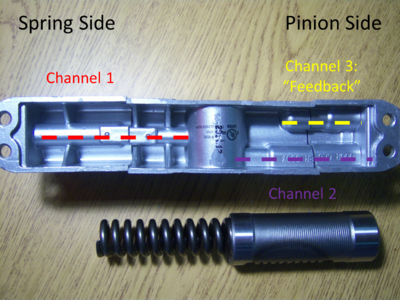
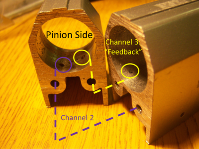
To prevent the spring from slamming the door closed, damping is used. The housing is filled with hydraulic fluid, which provides a resistance as the spring pushes the rack. Small channels at the bottom of the housing allow the fluid to travel to both sides of the rack. However, since all the fluid remains in the housing at all times, damping occurs during both directions of motion of the spring. To allow for more resistance in one direction over another, a feedback channel is utilized.
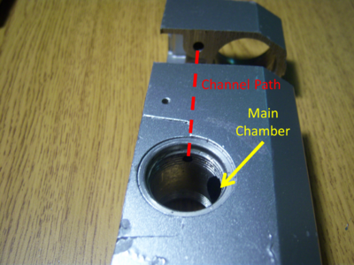
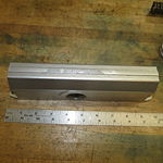
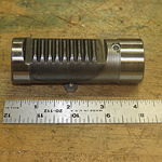
Close examination of the housing reveals that there are three channels. Two channels of the same size connect each end to the center, allowing fluid to move to the other side of the housing. The third, located on the pinion side of the housing, is shorter and returns to the main chamber before reaching the center. This third chamber acts as a feedback loop, and returns fluid to the chamber while the spring is expanding. This results in less displacement of fluid and more resistance as the door is closing. When the door is opening there is no resistance from feedback, and the fluid displaces more quickly. This complicated behavior of the fluid ensures that the majority of the damping occurs only as the door is closing and not as a consumer is trying to open it.
While there is some resistance from the fluid while a door is being opened, it is barely noticed by the consumer. However, when comparing opening a damped versus non-damped door, there is some more resistance in opening the one connected to a damper. Think of opening a bedroom door versus a door on a damper in a public place. It takes slightly more effort to open the door with the damper. This is in part due to the fluid resistance discussed above.
User Study
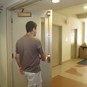
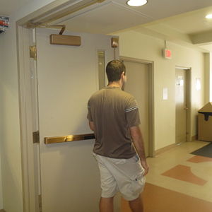
Industrial door closers are standard in their function. They can be adjusted for the angle to which the door is allowed to open, as well as the speed at which the door closes. They allow the door to open easily in a single direction and then damp the motion as the door closes in the opposite direction. The motion is usually stopped fully by the frame of the door.
Observations
- Shorter amount of time to push open a door than to pull (also easier when carrying things)
- Dampers protect walls from damage due to doors slamming
- If not damped enough the door can hit a person when closing
- Some people will fling door open as far as possible, so as not have to push door again as they walk through
- Greater effort is needed to open doors with dampers than without (adds resistance)
- Sometimes the door will be pushed open into a person on the other side
- Door does not remain open long enough for people carrying things
List of Parts
Design For Manufacturing and Assembly
DFM
Design for Manufacture analysis shows that the competitor’s door damper uses a number of custom parts in addition to several standard parts. Due to the number of custom components it is possible that a redesign could lead to a reduction in manufacturing costs and assembly time.
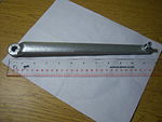
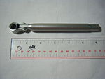
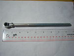
The custom parts include the arms of the linkage, as well as the shell, rack, and pinion. Several of these parts require complex machining processes. The arms must be threaded; the rack and pinion both require precise machining of their teeth and heat treatment. Such complex custom parts significantly increase the cost of manufacturing. Furthermore, tight tolerances must be followed in the manufacturing of the shell and caps in order to contain the hydraulic fluid.
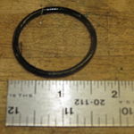
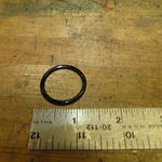
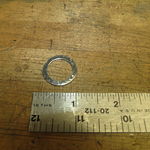
The design does make several attempts at using standard parts such as O-rings, screws, washers, and nuts. Furthermore, several of the custom parts are used multiple times to reduce the number of unique designs required.
DFA
Design for Assembly analysis shows that the use of custom parts has paid off in simplifying the assembly of the competitor’s door damper. Assembly is straightforward, requiring only a few simple rivets and a few threaded connections. However, several different tools are required, thereby reducing assembly simplicity and driving up cost. Assembly is further complicated by the use of hydraulic fluid. The fluid must fill the inner shell completely without gaps or bubbles in order for the product to function properly. While entirely filling the product is necessary it is likely to be a messy and time consuming process.
Failure Mode and Effect Analysis
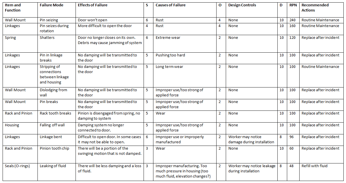
Failure Mode and Effect Analysis (FMEA) looks at potential reasons for failure during the use phase of the product. The table below outlines several potential failure methods. Each mode is ranked based on severity (S), probability of occurrence (O), and chance of being detected before failure (D). Each is ranked on a scale of 1-10 with ten being the most consequential. For severity it is the most harm to the user, for occurrence it is the most likely to occur, and for detection it is the least likely to be detected. The product of these three rankings is the Risk Priority Number (RPN). The Risk Priority Number provides a relative ranking system for the different potential failure modes.
The table below ranks the failure modes from highest to lowest RPN. The highest severity ranking of 6 was given to two entries because of the potential for the door to be jam closed. This could potentially cause a dangerous situation for the user. Most other methods of failure either result in a door opening with more resistance or a door disconnected from the damping system. While both are inconvenient for the user, it does not provide an immediate danger. All occurrences were ranked between a 2 and a 4, suggesting a low probability of occurring. The door damper has a twenty five year warranty. A long lifetime gives an increased chance of an occurrence, hence a lower ranking was not given. All detection was ranked a ten, or not able to be detected, because most failures are a direct result of an action by the user, which can not be detected beforehand.
The two highest failure modes for the door damper involved rust occurring on either of the two pins in the linkage system. The pin connecting the two links has the potential to do the most damage and is ranked the highest. If this pin were to rust enough, it would seize the system and prevent the door from opening. However if the pin connecting the linkage to the door rusted, it could still be opened, just with increased resistance. A rigorous routine maintenance system could allow for early detection instead of waiting for an incident to occur. Other failure modes involve parts breaking from improper use of the door. Slamming the door open or pulling on the linkages will cause the parts to deteriorate over time. Replacing the parts as needed is the most sensible solution for this problem.
A potential solution for wear over time is to make the system more robust. To prevent the door from being slammed open, a two way damper system could be implemented. Ideally there would only be damping on an opening door as it nears fully opening, thus not introducing extra resistance to a user. However, potential trade offs are a much more complex damping and linkage system and more resistance to a user while opening the door. While a two way damper could potentially improve the life of the door damper, the potential complexities have to be looked into before implementation.
Design for Environment
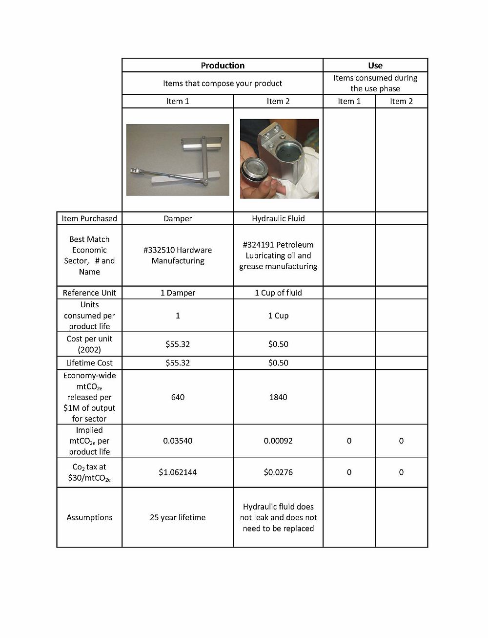
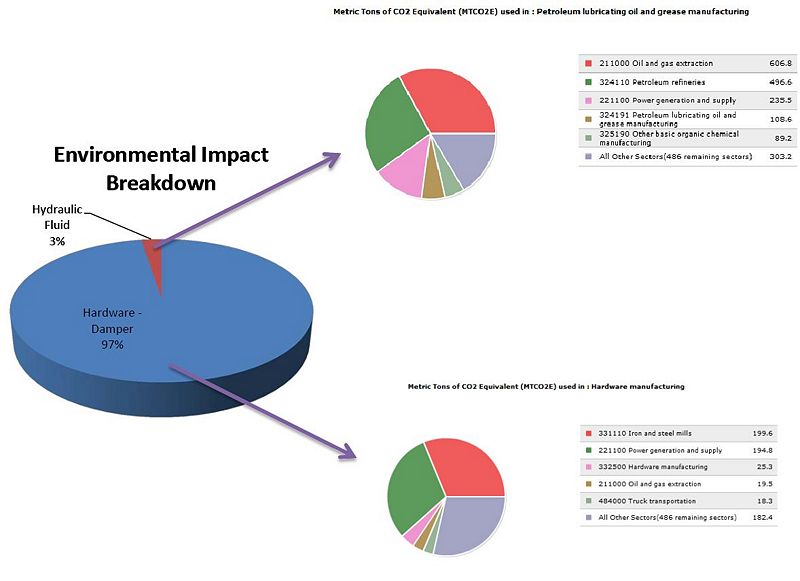
Through the process of studying the commercial grade door damper, we did not discover the use of any materials or substances that are especially harmful to the environment. There are only three different materials included in the door damper - steel, aluminum, and hydraulic fluid. Through a Economic Input-Output Life Cycle Assessment, it was found that the majority of green house gases associated with the life cycle of a door damper are produced during the production of steel from Steel Mills, while the second greatest source is from the power generation and supply for all of the energy used during the complete manufacturing process of a door damper. As can be seen in the table below a greenhouse gas emissions tax would be only slightly over $1. Since the door damper as a unit cost nearly $70, this tax is not a significant portion of the price of a door damper unit.
As can be seen in the chart below, the large majority of the green house gas emissions come from the production of the hardware portion of a door damper. One way to decrease the environmental impact of this product, would be to design a door damper that contained fewer parts, less mass, and less material overall. Although the use of hydraulic fluid is not ideal when taking environmental impact into consideration, it is the manufacturing of the hardware, and not the hydraulic fluid, that is responsible for the majority of the greenhouse gases emitted during the lifecycle of a door damper.
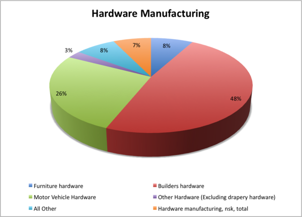
The EIO-LCA Analysis was performed using the Carnegie Mellon Green Institute tool available at eiolca.net. The sector chosen for the hardware portions of the door damper was 'Hardware Manufacturing.' The door damper falls into the category of 'Builders' Hardware,' which makes up 48% of the Hardware manufacturing sector. Although there is not a category that specifically mentions a door damper, the processes used for the production of nearly all of the types of hardware would be quite similar, therefore this sector represents the greenhouse gas contribution of a door damper reasonably well. The breakdown of this sector can be seen in the chart below.
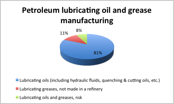
The sector chosen for the hydraulic fluid was 'Petroleum Lubricating, Oil and Grease Manufacturing.' As can be seen in the breakdown chart below, 'Lubricating oils (including hydraulic fluids, quenching & cutting oils, etc.)' makes up over 80% of this sector. The chosen sector represents the greenhouse gas emissions due to the production of the hydraulic fluid very well.
Team Members
Team members worked together in order to best utilize everyone's individual strength. Cooperation proved key to providing a quality product by deadline.
Leader : Essian Ohues
DFMA Lead : Michael Saitta
FMEA Lead : Stephen Poniatowicz
DFE Lead : Jillian Wollenberg
Presentation Leader : Bushra Salama
