Lamp stand mechanical arm
From DDL Wiki
Contents |
Executive Summary
The lamp that we dissected was purchased for only ten dollars. It was designed for low manufacture cost so that it could be purchased at a low cost. In doing so, aesthetics and some safety were sacrificed. We chose this lamp because it appeals to our target markets, which are college students and universities.
The main stakeholders in this lamp are the manufacturing department, the assembly and packaging department, the retail department, and the consumers. All of the stakeholders play a large role in the success of this lamp. The only consumer needs that are met by this lamp are its low cost and decent lighting. This lamp is difficult to put together; the base is confusing and isn't very sturdy.
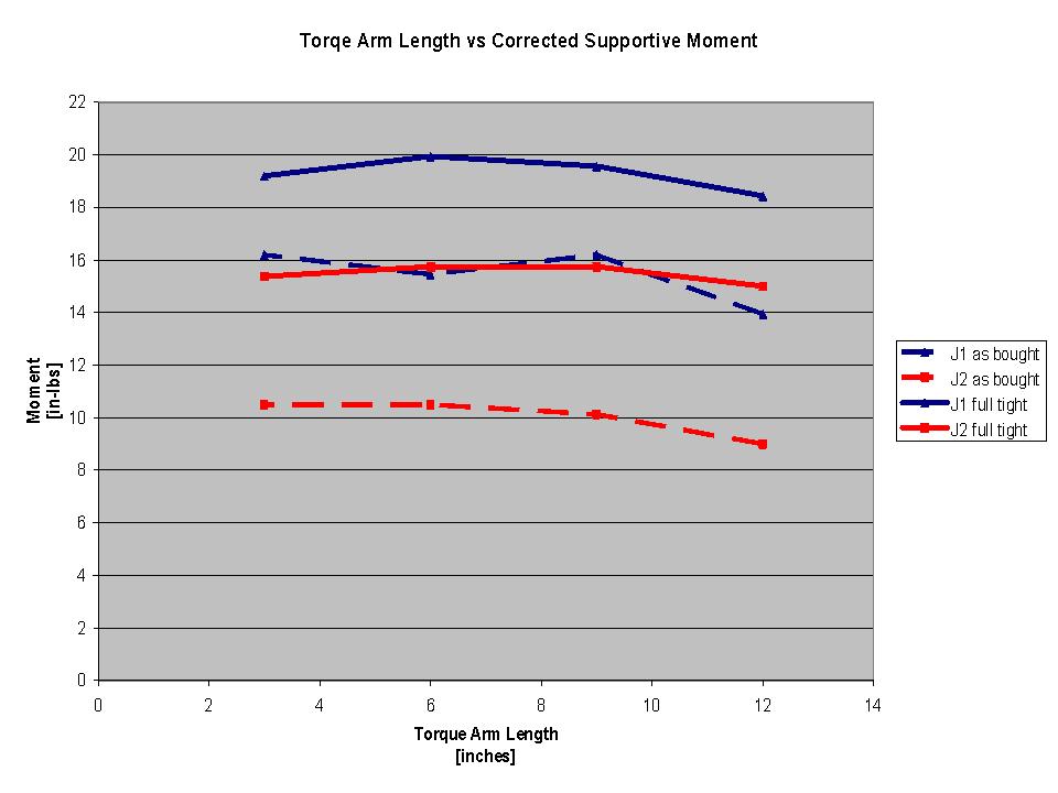
The mechanical analysis determined the strength of the bottom joint and the middle joint. A force was applied to three different locations on each arm and it was measured with a spring scale. The force required to cause motion in the lever arm at each location was recorded. It was found that torque is relatively independent of the length of the torque arm and that the middle joint has a greater supportive moment than the lower joint does.
The lamp dissection was a little difficult. It was hard to get the electric cord out of the cord containing rods. It was also difficult to take apart the light socket because of the ceramic that was poured around it. However, some parts were easy to take apart like the base and the joints.
The lamp was designed well for manufacturing and assembly. The design of this lamp included cheap, easy to manufacture parts as well as parts with unambiguous assembly orientation. However, this lamp is not designed for disassembly. The difficulties encountered in the dissection of this lamp showed disassembly problems. This lamp is also not designed for the environment. The parts are not easy to recycle or reuse once disassembled.
We hope to design a lamp that has improved aesthetic and safety properties. It is ideal to stay in the same manufacturing and assembly direction as the lamp we dissected. However, there are many things that can be improved in the disassembly process. Our design will be better, stronger, and brighter.
Stakeholders
- Manufacturing
- Meeting tolerances set by designer
- Decrease variation when manufacturing part
- Safety of the shop floor is maximized, while keeping costs as low as possible and completing parts in a reasonable time frame
- Should choose the machinery to manufacture part since they have the most experience with the manufacturing process
- Matching the capability of the machinery to the requirements for the part to avoid excess cost
- Minimize the number of steps in the manufacturing process and creating easy transitions from one manufacturing process to the next
- Assembly and Packaging
- Efficient assembly procedure in place
- Clear instructions on how to assemble
- Minimal variety of tooling used
- Since tooling is cheap, have a supply of back up tooling
- Ensure correct tool is used for the task at hand. For example ensure the screwdriver can fit perfectly into the screw’s head
- Create a testing scheme to ensure the quality of the product released to the public.
- minimize the volume the product takes up to decrease size of container
- Minimize weight to decrease shipping cost
- Provide labels on package such that consumer can quickly identify if the product can meet the need of the consumer
- Retail
- Small packaging to allow for less space taken up on the shelf
- Light weight for easy movement
- No fork lift required for movement of product in bulk
- Low bulk purchase cost
- Reliable to ensure minimal product returns or exchanges
- Consumer
- Low cost option relative to utility obtained from product
- Precise placement of light source can be obtained throughout the life of the lamp.
- Stable fixture for light source
- Eliminate the need to touch hot surfaces while lamp is in use
- No assembly required. If it is required no tooling or instructions required
- Movement of light source can be obtained with minimal force needed.
- Aesthetically appealing
- No injury incurred while using lamp
- Maximum brightness of light source to illuminate large area
- Light source (bulb or LED) should not be visible to the user during normal use
- Easy on/off mechanism
- Long cord, but short enough so it does not cause too much apparent clutter.
- Light weight and easy to transport
- Packaging with sufficient information to ensure product can meet needs of customer
Use of Lamp
The steps to using our lamp is as follows:
Assembly of Lamp
1. Open the box and remove the dissembled lamp from the box. Undo the twist ties holding the wires together and remove the pieces of the clamp from the sealed bag.
2. Match the groove on the lamp hood's base with the tab on the inner diameter of the light bulb socket cover. Insert the lamp hood in the light bulb socket cover and twist counter-clockwise to secure in place.
3. Extend the lamp arm such that the lamp hood is sufficiently far from the male connector on the opposite end of the mechanical arm. Place on the side.
4. Insert the clamp base into the elbow screw with the teeth pointing toward the elbow screw.
5. Insert the base clamp knob nut into the base clamp knob and screw into the elbow knob.
6. Insert the elbow into the small lower hole of the base. Attach this onto a surface by turning the base clamp knob till a "secure" fit is obtained.
7. Insert the male portion of the lamp into the female base.
8. Connect the lamp to a power source.
9. Turn on the lamp.
Use of Lamp
1. To Extend the lamp such that it is over the workspace, loosen the friction knobs such that the lamp will be held up by the knobs, but will allow for it to be maneuvered. Alternatively move the lamp by tightening and loosening the friction knobs may be when a new position for the lamp is desired.
2. Grasp the lamp shade hood (while cool only) and move the lamp to the desired position. If the lamp shade is hot, move the lamp by moving the mechanical arms taking care not to get pinched. Use a cloth to grasp the lamp shade hood and maneuver the hood to the needed.
System Function
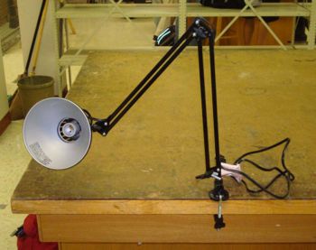
The system is a mechanical arm that uses frictional joints to support a lamp.
The Base
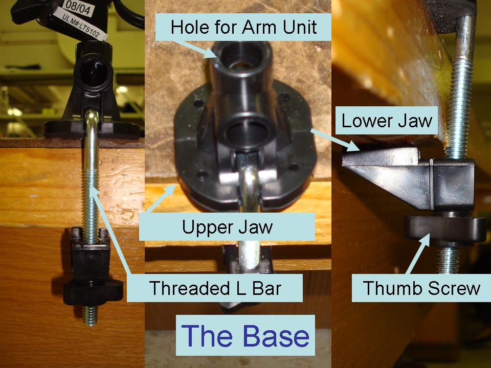
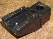
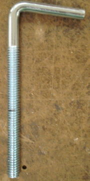
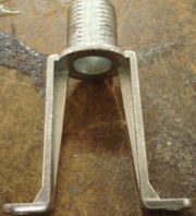
The lower jaw, the threaded L bar, the thumb screw, and the upper jaw make up the base. The base unit attaches to the edge of a desk or table with the lower jaw positioned below it and the upper jaw on top. The threaded part of the L bar goes through the lower clamp then the wing nut while the shorter, unthreaded part goes through the upper clamp. The screw is used to tighten down the clamps and secure the clamp assembly to the table, fixing it from all translations and rotations. There is a hole at the top of it for a peg at the base of the arm unit.
Arm Unit
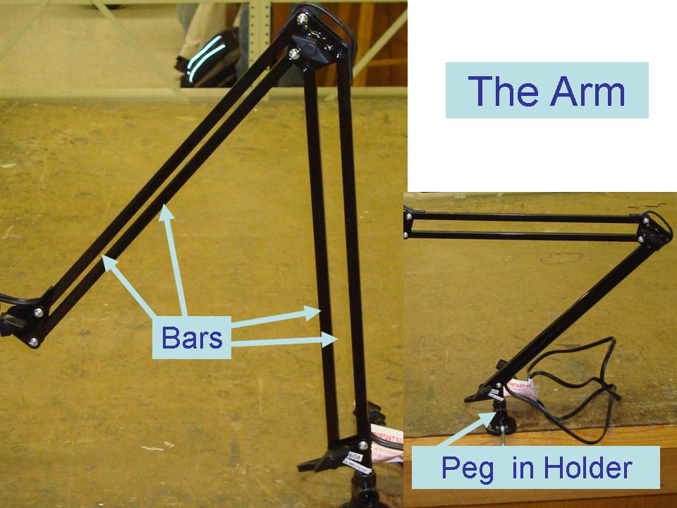
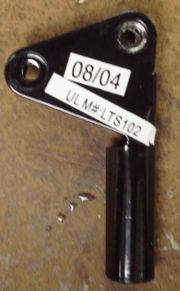
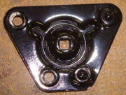
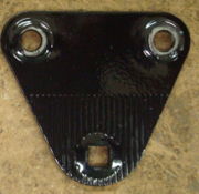
The arm has two parallel sets of equal bars that rotate at either end where it connects to plates that hold them in position relative to one another. The bottom holder has a peg on the bottom that inserts into the top of the top clamp in the base. Two of the bars attach to the bottom holder and run parallel up to the next set of joining plates. From these plates, two more bars run out of equal length up to another set of plates. These plates hold a fixture that rotates in the plane of the arm and holds the base peg of the plan unit. With this configuration of members, the top of the arm can move within a single plane that contains all the plates and members, allowing it to position along the two axes in the plane. There are screws at each joint that can be tightened to increase the friction in the joint to hold the arm in its current position.
Lamp Housing Unit
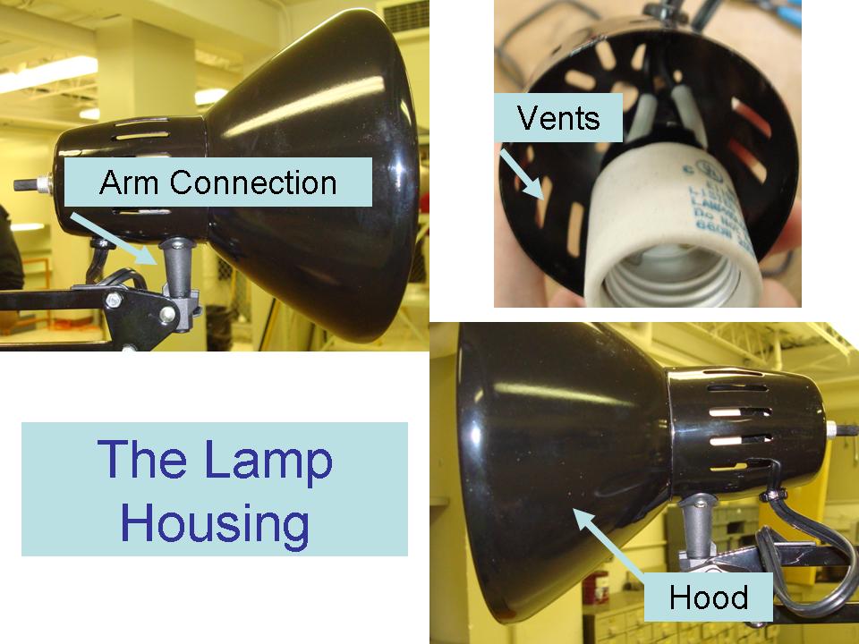
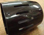
The lamp housing attaches to the arm with a peg that can rotate about its axis. This peg is screwed to the metal cup shaped housing that holds the fixture that the light screws into. There are holes cut in this part to allow heat dissipation from the lamp. A bowl shaped metal part is inserted and twisted into the opening of the cup to attach it. It serves to focus the light emitted from the bulb so that it may be directed and prevent it from blinding the user.
The Electrical Unit
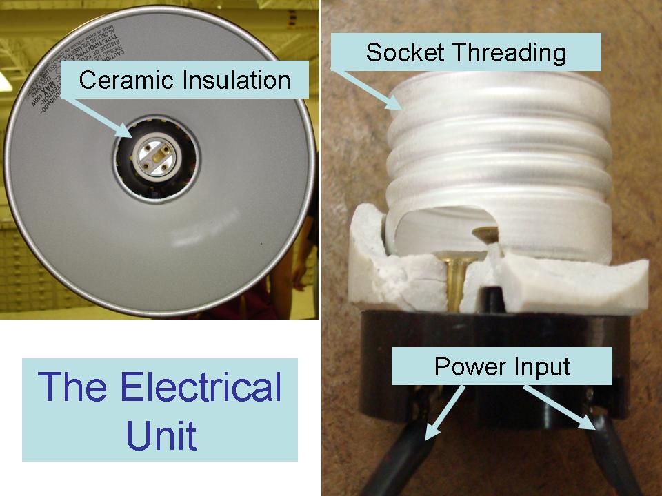
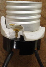
The electrical unit has its most complex components within the Lamp Housing Unit. There is a threaded metal part that is made to allow for the insertion and securing of a light bulb. This part is riveted to a ceramic isolative part and further through to the switching assembly. The switch, when rotated, turns a small pin normal to its axis, causing it to contact two metal fingers, completing the circuit to turn on the lamp. To this switching assembly runs the power cable from outside the cup of the lamp housing to the switching assembly to provide power to the system. This cable runs down the upper members of the arm unit to the base of the arm unit where there are an additional six feet of cable with a typical 2 prong AC plug.
Mechanical Analysis
For the lamp fixture, one of the mechanisms essential to its operation is its friction joints. In the design process, there is a relation between how robust the joints are and the weight they can support and what it costs; A more robust joint that can support more weight will cost more and decrese the effective weight held by all previous joints in the mechanism. What is desired from this study is to find the supportive moment supplied by the current mechanisms and in looking ahead, make educated decisions in the design of our new product that will likely start with some structure of an arm mechanism and have similar components, but joints adapted to support our desired payloads without over-engineering and additional cost.
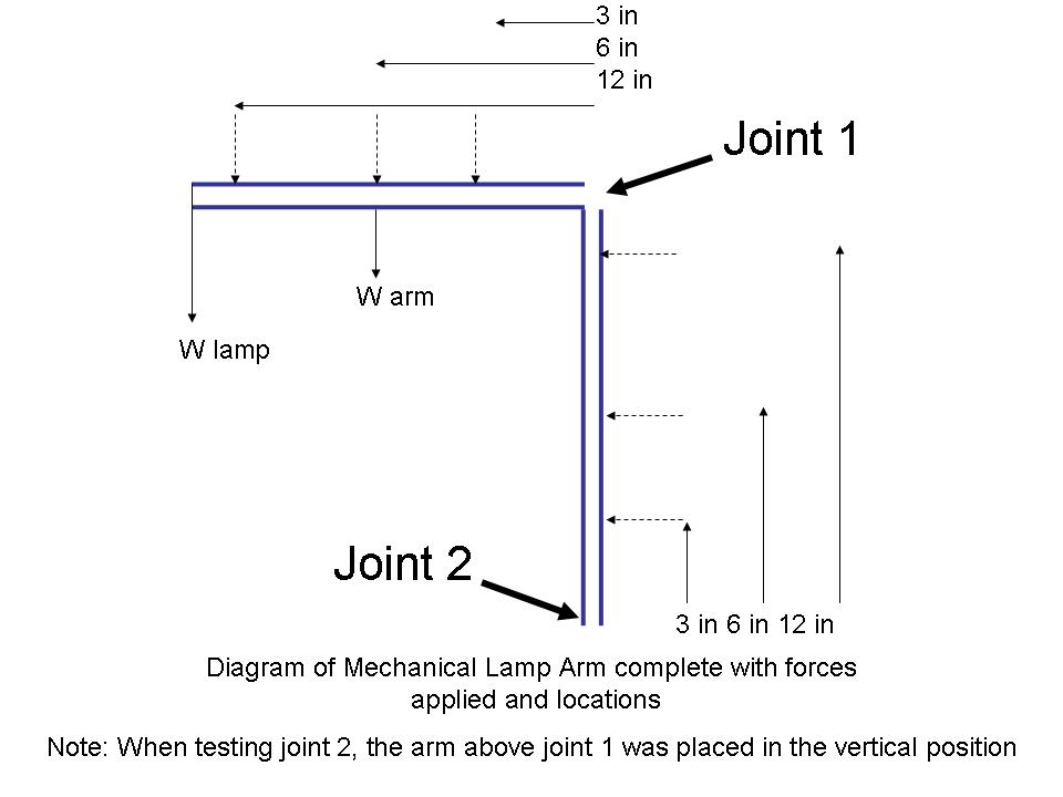
The tests in the mechanical arm were preformed on two different joints, one where a plastic wing nut was tightened down onto a single folded metal plate (Joint 2) and another where a plastic nut is tightened down onto a set of two independent metal plates (Joint 1). This study will show what supportive moment may be provided by the current design so that we may design our joints appropriately in the new design.
Using the weights from the Bill of Materials, the mass of the upper arm components was removed from the system when testing joint 1 such that the moment shown below reflects only the supportive moment supplied by the friction on the two independent metal joints on the bars. For testing joint 2, the upper part of the arm was in the vertical position in order to remove any moment from components, as noted in the figure below. The moment shown for joint 2 reflects the supportive moment supplied by the friction between the single bent metal sheet and the bars.
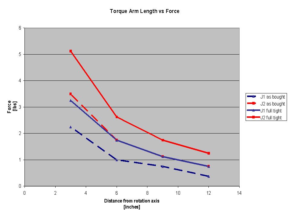
The initial study was preformed and the data collected as in the graph below. This graph shows the force required to cause motion in the mechanism against the length of the torque arm used. We know that T = dF where T is the torque applied, d is the length of the torque arm and F is the force applied at t he location. Given this function, assuming that the same torque needs to be applied at any location to disrupt the friction, then dF should stay constant and result in a linear graph. The first graph at the right confirms this phenomenon relatively well, indicating that the data is good for further analysis.
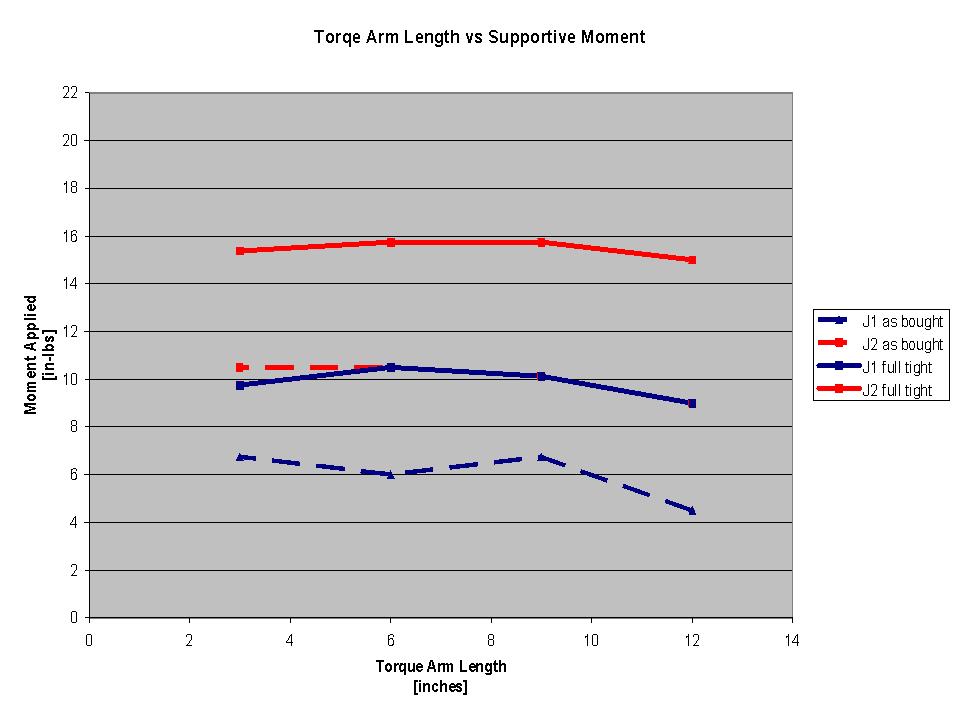
From this data, the torque applied was plotted against the length of the torque arm to check if the torque necessary was independent of the length of the torque arm (which is not always true in an unideal situation). The graph below confirms that the torque is relatively independent of the length of the torque arm, so we can continue finding what the moment is supplied by the screws in the joints.
Due to the orientation, Joint 1 had additional loading on it beyond just the force applied using the spring scale which included the weight of the lamp fixture and the weight of the arm. In the case of joint 2, there was no additional loading. To account for this effect, the torques applied by the various components were computed from the weights collected during disassembly and the physical location from the fulcrum of the joint. The resulting torques were added to the torque applied to create the third chart of the actual maximum moments able to be supported by the joints.
The results are that the best material to maximize support is a plastic nut on a set of independent plates, and that in the case of the current model, a maximum torque of about 19 in-lbs, meaning that a mass of about 1.5 lbs could be supported at the end of the arm.
This analysis has shown that while the arm is sufficiently strong to support the small weight of a light bulb, it may not be sufficiently strong to support the weight of some of the other accessories that we wish to place on the arm, such as a GPS Unit or a clipboard. For this reason, when we redesign the arm, we will need to do one of the following:
- Decrease the length of the arm segments so as to decrease the effective torque on the joint resulting from the payload.
- Increase the strength of the supportive moments in the joints by adding springs or better frictional or locking mechanisms.
Components
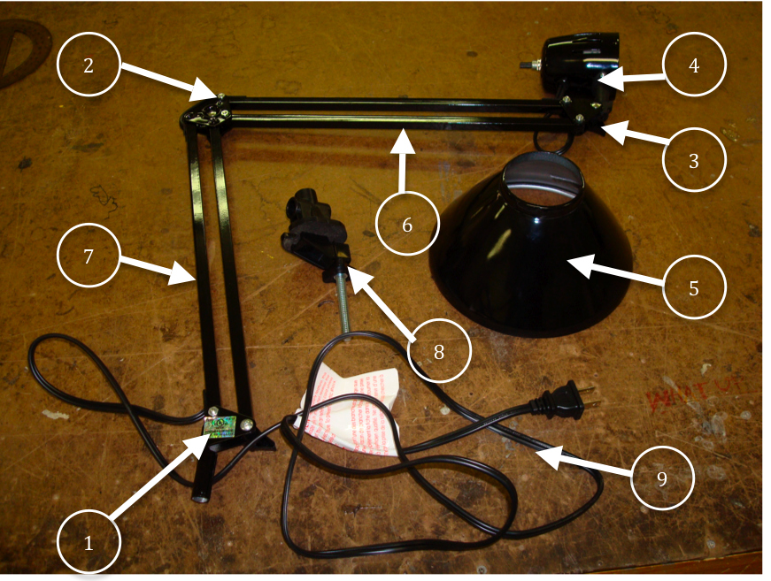
The exploded view below shows the major components of the lamp. Following is a chart that shows every single component of the lamp down to the screws and nuts. During the dissection, it was particularly difficult to take apart the light socket because of the ceramic that was poured around it and the electrical wires that were riveted to the socket. It was also difficult to remove the electric cord from the cord containing rods.
- Joint 1
- Joint 2
- Joint 3
- Lamp Head
- Lamp Hood
- Non cord containing rod
- Cord containing rod
- Base
- Electric cord
| Part # | Part Name | Qty | Mass (g) | Function | Manufacturing Process | Material | Image | |
|---|---|---|---|---|---|---|---|---|
| 01 | Electric Cord | 1 | 114 | to transmit electricity from outlet to lightbulb | extrusion, cutting | aluminum, plastic, electric wires | ||
| 02 | Non Cord Containing Rod | 1 | 48.19 | to increase distance from base to lightbulb | extrusion, machining | aluminum | ||
| 03 | Cord Containing Rod | 1 | 45.36 | to increase distance from base to lightbulb and contain electric cord | extrusion, stamping, machining | aluminum | ||
| 04 | Lamp Hood | 1 | 158.76 | to project and focus light from lightbulb | stamping | aluminum | ||
| 05 | Base | 1 | 17.01 | to mount lamp on a flat surface | injection molding | plastic |
| |
| 06 | Base Clamp | 1 | 8.5 | to hold base onto a flat surface | injection molding | plastic | ||
| 07 | Elbow Screw | 1 | 39.69 | to adjust clamp on base | pressing, tapping | aluminum | ||
| 08 | Cord Containing Rod End Cap | 4 | 0.9355 | to cover end of rod and to guide electric cord | injection molding | plastic | ||
| 09 | Non-Cord Containing Rod End Cap | 4 | 0.4706 | to cover end of rod | injection molding | plastic | ||
| 10 | Joint 1 | 1 | 22.68 | to attach lamp to base and adjust position | stamping | aluminum | ||
| 11 | Joint 2 | 2 | 14.18 | to attach bottom rods to top rods and adjust position | stamping | aluminum | ||
| 12 | Joint 3 | 2 | 5.67 | to attach lamp arm to lamp head and adjust position | stamping | aluminum | ||
| 13 | Friction Knob | 3 | 2.835 | to tighten joints and hold joints in place | injection molding | plastic | ||
| 14 | Friction Knob End Cap | 3 | 0.4706 | to cover ends of screws for friction knobs | injection molding | plastic | ||
| 15 | Small Nut | 8 | 1.418 | to hold screws in place | pressing, tapping | aluminum | ||
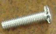
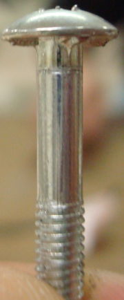
| 16 | Small Screw for Joints 2 & 3 | 5 | 2.835 | to hold joints together | pressing, tapping | aluminum | ||
| 17 | Joint 1 Knob Screw | 1 | 2.835 | to hold friction knob in place | pressing, tapping | aluminum | ||
| 18 | Joints 2 & 3 Knob Screw | 2 | 2.835 | to hold friction knob in place | pressing, tapping | aluminum | ||
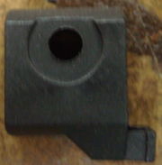
| 19 | Light Bulb Socket Cover | 1 | 53.00 | to guard electronics and hold light switch | stamping | aluminum | ||
| 20 | Light Bulb Socket | 1 | 42.00 | to connect lightbulb to lamp and power | stamping, pressing, tapping, saudering | aluminum, copper, ceramics, electrical wires & components | ||
| 21 | Lamp Head Connector | 1 | 5.670 | to connect lamp head to joint 3 | injection molding | plastic | ||
| 22 | Lamp Head Connector Screw Holder | 1 | 1.418 | to contain screw that connects to Joint 3 friction knob | injection molding | plastic | ||
| 23 | Light Switch | 1 | 2.835 | to turn light on and off | injection molding | plastic | ||
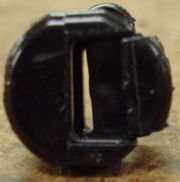
| 24 | Cord Clip | 1 | 1.418 | to connect electric cord to light bulb cover | casting, molding | plastic | ||
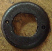
| 25 | Cord Clip Ring | 1 | <0.01 | to make area around cord clip look nice | injection molding | plastic | ||
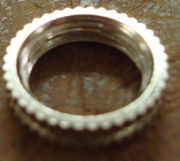
| 26 | Light Switch Ring | 1 | 1.418 | to connect light switch to light bulb cover | extrusion, cutting, tapping | aluminum | ||
| 27 | Light Switch Connector | 1 | 7.088 | to connect light switch to light bulb socket | extrusion, stamping | aluminum | ||
| 28 | Light Switch Connector Screw | 2 | 0.7088 | to hold light switch connector to lightbulb socket | pressing, tapping | aluminum | ||
| 29 | Lamp Head Connector Gasket | 1 | 1.418 | to go between lamp head and lamp head connector | cutting, stamping | aluminum | ||
| 30 | Lamp Head Connector Screw | 2 | 0.7088 | to hold lamp head connector to lamp head | pressing, tapping | aluminum | ||
| 31 | Light Switch Spring | 1 | <0.01 | to hold light switch in on/off positions | molding, cutting | brass | ||
| 32 | Light Switch Spring Pin | 1 | <0.01 | to resist light switch spring | pressing, tapping | brass | ||
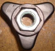
| 33 | Base Clamp Knob | 1 | 1.418 | to adjust distance between base and base clamp | injection molding, tapping | aluminum, plastic | ||
| 34 | Base Clamp Knob Nut | 1 | 2.835 | to thread base clamp knob onto elbow screw | pressing, tapping | aluminum |
Design For X
There are many different considerations when designing a product. This section describes the relevant concerns, and how we have seen them addressed in the creation of this lamp.
This lamp is well designed when looked at a manufacturing and assembly perspective. There are few areas for improvement here, and those that exist are less important then issues found in the other design areas. Therefore, it is our recommendation that improvements to this lamp should be focused on the areas of disassembly and environmental impact.
Design For Manufacturing (DFM)
DFM is a process that optimizes a product for manufacturability. The main considerations of DFM are reducing production cost such that the product is cheaper to manufacture and simplifying the design such that it is easier to manufacture.
This lamp was well designed for manufacturing with a large production volume. It is a simple design, and uses cheap, easy to manufacture parts, and common industry parts. Pieces are easy to manufacture in very large batches. Our only recommendation here is that one standard type of screw should be used instead of the current three.
Ways that DFM has been used to design this lamp:
- The design is very simple, with few parts. A handful of screws hold the whole lamp together.
- The four rods in the lamp are created the same way, through extrusion, allowing the same machine to construct all of them. The one small difference between the cord containing rods and non-cord containing rods is in a small amount of machining.
- Screws are standard sizes which are easy to buy from manufactures.
- The cord runs through an already hollow rod, allowing the rod to fulfill multiple functions.
- The lamp hood is removable allowing for smaller packaging.
- Cheep metals and plastics were used in fabrication
Design for Assembly (DFA)
In DSA, the goal is to optimize the assembly process. Care is taken to make parts easy to attach, and to make the assembly sequencing clear.
The DSA process was well thought through for this lamp. Among other things assembly is unambiguous and fasteners have been limited. Although there is very little to improve on with DSA, one small suggestion would be to redesign the quadrilateral joints, as it is easy to confuse them or insert them in the wrong direction.
Ways that DSA has been used on this lamp:
- Unambiguous, assembly orientation.
- The part count has been minimized, a handful of screws hold the whole lamp together.
- The electrical cord and plug is a subassembly, able to be inserted quickly.
- The number of fasteners has been minimized. The lamp hood twits into place, the lamp sets into the base, and the cord is held in place by the end caps for the rods.
- Handling is minimized as the small number of parts with few places to fasten them makes the assembly process flow.
Design for Disassembly (DFD)
In DSA, the goal is to optimize the disassembly process. Care is taken to make parts easy to disassemble, and to make it easy to remove expensive or hazardous parts first such that they and be dealt with and the rest dealt with as need be.
The lamp designers did not make DFD a priority when it was first designed. This is observable in how the pieces are attached in ways that are hard to undo. We have a few suggestions in how the to make this product easier to disassemble.
Suggestions
- A huge difficulty is encountered with the tight fitting end caps on the rods. They are hard to remove, and require much force and effort. Slightly looser end caps would make disassembly much easier.
- The cord threaded through the rods makes disassembly difficult as well, as pieces stay attached unless the cord is cut.
Design for Environment (DFE)
DFE is a process by which the environmental impact is considered, both in the creation of the product when materials are chosen and in thinking of what the fate of the product will most likely be at the end of it’s life. Environmental impact is sought to be lessened, both by making the product easy to disassemble and by using materials that are produced in an environmentally safe way and which can be recycled.
There is much one can do with this lamp when using DFE. Many of the problems we observed stem from the lamp being hard to disassemble.
- The difficulty in disassembling makes it difficult to recycle parts, as the most economical end of life action is throwing the lamp away.
- The difficulty in disassembling makes it difficult to repair as well, causing the less-sustainable practice buying a new lamp instead of repairing the old one.
- In particular, the light bulb socket must be thrown out since it is practically impossible to disassemble and reuse
- Although we have a limited knowledge of the materials used, it is assumed that it would be possible to buy parts that are more environmentally friendly.
- The rods are painted, which makes them harder to recycle. Using unpainted metal would make this process easier.
Life Cycle Assessment
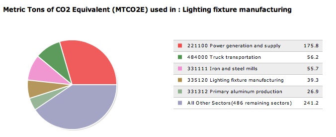
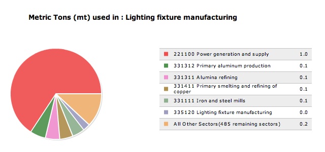
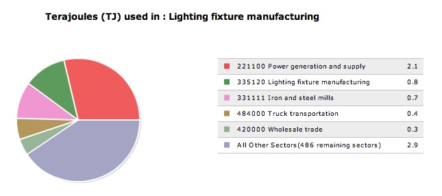
Economic Input Output Life Cycle Assessment (EIO-LCA) looks at the economics of certain sectors in order to determine environmental impact. The sector used for this product was Lighting Fixture Manufacturing. This was assumed to be a reasonable choice because “Residential-type electric lighting fixtures (except portable), including parts and accessories” combined with a couple smaller categories describing this lamp took up 21% of the sector and the remaining items listed were made from similar materials. All the numbers on the following graphs are based on $1 million spent in the Lighting Fixture Manufacturing Sector.
(Greenhouse Gasses Graph, created using www.eiolca.net)
Using the Purchaser Price model on the EIO-LCA website, it can be seen that the sectors which release most of the greenhouse gasses and air pollutants associated with producing this lamp are Power Generation and Supply and Truck Transportation.
(Conventional Air Pollutants Graph, created using www.eiolca.net)
In the Conventional Air Pollutants graph, Power Generation and Supply plays a stronger role. Although there are other factors, in this area POwer Generation and Supply dominates. This means that the materials used to produce this lamp, something that we have easy control over, does not have as much of an impact on pollutants as the energy used to produce it.
(Energy Graph, created using www.eiolca.net)
Power Generation and Supply is one of the leading energy uses, followed by Manufacturing and Materials.
On average, this lamp is assumed to be used about three hours a day. This number comes from user input on how long they leave their lamps on each day. This lamp will only last for a year before breaking, which gives 1095 hours of use a year. Taking an average 40 Watt bulb, that makes for 43.3 kWh a year. The EIO-LCA for Power Generation and Supply shows that 9530 MTCO2 are emitted per $1 million. With the average price of power at $0.12, that means 0.05009 MTCO2 are emitted with the use of each lamp. The EIO-LCA for Lighting Fixture Manufacturing shows that 170 MTCO2 are emitted per $1 million. With each lamp costing $10, that means 0.017 MTCO2 are emitted with the manufacturing of each lamp.
The best way to reduce environmental impact is out of the control of Initech: since the use phase consumes more energy then the manufacturing phase, using light bulbs with a lower Wattage would make a huge difference, but this decision rests in the hands of the user. Using a machining process that used less energy would lessen environmental impact. Initech may not be able to change the manufacturing process directly, but they could use DFM to help this process. As already stated, however, this lamp seems to be already well designed for manufacturing. A second tactic would be to find materials that have a less hurtful affect on the environment. Although we are unclear of exactly the type of plastics used to create the molded parts, at a guess, a more environmentally friendly plastic or metal could be used in it's stead. Smaller packaging, which would result in more lamps being able to fit on a truck would also help to cut down on greenhouse gasses emitted.
Failure Mode and Effects Analysis (FMEA)
FMEA is a process by which potential failures are identified and evaluated. We have identified a number of possible failures, by far the most crucial being the base. This lamp does not secure into the base, and during normal use and maneuvering it will regularly separate itself from the base. This may result in inconvenience as the user has to completely reposition the lamp, or it may result in the lamp being broken to the point of no longer being able to function. We recommend reconsidering what we see as an fundamentally flawed design. The new design should, by means of a pin and grove or other simple mechanism, be able to keep the lamp secured to the base while in use.
Outlined below are several problems we found concerning when analyzing this product. Please not that our RPN is an estimate.
| Item | Function | Failure Mode | Effects of Failure | S | Causes of Failure | O | Design Controls | D | RPN | Recommended Actions | Responsibility & Deadline |
|---|---|---|---|---|---|---|---|---|---|---|---|
| Electric Cord | to transmit electricity from outlet to light bulb | loss of or no connection at plug end | lamp will not light | 8 | fault of cord manufacturer | 3 | check cords before assembly | 2 | 48 | - | controls engineer |
| fire start | 9 | fault of cord manufacturer | 1 | check cords before assembly | 2 | 18 | -reevaluate connection such that a broken connection will not start a fire | mechanical engineer | |||
| loss of or no connection at lamp end | lamp will not light | 8 | person connecting the two did a poor job | 3 | check connection after assembly | 2 | 48 | - | controls engineer | ||
| fire start | 9 | person connecting the two did a poor job | 1 | check connection after assembly | 2 | 18 | -reevaluate connection such that a broken connection will not start a fire | mechanical engineer | |||
| Non-Cord Containing Rod | to increase distance from base to light bulb | cracks in rod | rod is less strong | 3 | lamp bumped or fell on it's own | 5 | make rod out of a stronger material | 1 | 15 | - | customer |
| 3 | rod too thin to withstand normal use | 3 | check thickness of rods coming off assembly line (quality control) | 3 | 27 | reevaluate minimum thickness of rods | materials engineer | ||||
| rod breaks | lamp can not stay where put | 7 | lamp bumped or fell on it's own | 3 | make rod out of a stronger material | 2 | 42 | make sure potential uses are studied in depth | designer | ||
| Cord Containing Rod | to increase distance from base to light bulb and contain electric cord | cracks in rod | rod is less strong | 3 | lamp bumped or fell on it's own | 5 | make rod out of a stronger material | 1 | 15 | - | materials engineer |
| 3 | rod too thin to withstand normal use | 3 | check thickness of rods coming off assembly line (quality control) | 3 | 27 | reevaluate minimum thickness of rods | materials engineer | ||||
| rod breaks | lamp can not stay where put | 7 | lamp bumped or fell on it's own | 3 | make rod out of a stronger material | 2 | 42 | make sure potential uses are studied in depth | designer | ||
| wires exposed | 3 | poor job connecting end caps | 3 | quality control | 3 | 27 | - | controls engineer | |||
| Lamp Hood | to project and focus light from light bulb | Bent hood | less pretty | 4 | lamp falling to the floor or otherwise being mishandled | 5 | make hood out of stronger material | 1 | 20 | - | materials engineer |
| Base | to mount lamp on a flat surface | seperation of the lamp from base, lamp falls | lamp is partially broken or cracked | 7 | normal movement of lamp | 10 | design is fundamentally flawed | 4 | 280 | redesign of base | designer |
| lamp is broken | 8 | normal movement of lamp | 8 | design is fundamentally flawed | 4 | 256 | redesign of base | designer | |||
| cracks | lamp will attach poorly to desk | 7 | too much force used when clamping lamp | 4 | run tests to see how much force will break lamp | 3 | 84 | redesign part such that it can withstand more force | mechanical engineer | ||
| Base Clamp | to hold base onto a flat surface | cracks | lamp will attach poorly to desk | 7 | too much force used when clamping lamp | 4 | run tests to see how much force will break lamp | 3 | 84 | redesign part such that it can withstand more force | mechanical engineer |
| Friction Knob | to tighten joints and hold joints in place | no longer holds joints in place | lamp will not stay where put | 7 | fatigue | 2 | Failure observed by user | 3 | 42 | redesign friction knob for longer lifespan | mechanical engineer |
| 7 | user turning it too tightly and then forcing joints to move | 1 | Failure observed by user | 3 | 21 | redesign friction knob for longer lifespan | mechanical engineer | ||||
| Light Bulb Socket | to connect light bulb to lamp and power | electrical failure | lamp will not turn on | 8 | poorly poured ceramics | 2 | quality control | 5 | 80 | - | controls engineer |
| 8 | wires disconnect | 2 | quality control | 5 | 80 | redesign light bulb socket such that failing to properly connect the wires is difficult | mechanical engineer | ||||
| Light Switch Spring | to hold light switch in on/off positions | spring becomes tired and will no longer work | light won't turn on/off | 7 | fatigue | 3 | Failure observed by user | 3 | 63 | redesign spring for longer lifespan | mechanical engineer |
Each potential failure is looked at based on the severity of the problem (S), it’s occurrence (O), and how easy it is to detect (D). For each of these criteria, a number is assigned between one and ten. One is always the ‘good’ side of the spectrum: the problem is not severe, the occurrence is rare, and it is easy to detect. Ten is the ‘bad’ side of the spectrum. Multiplied together, these numbers form the Risk Priority Number (RPN). A higher RPN means that problem is more of a risk.
Team Member Roles
We divided up the work of this report as follows:
- Adam Aaron: System Function and Mechanical Analysis
- Gwendolyn Barr: Design For X, Life Cycle Assessment, and Failure Mode and Effects Analysis
- Raysel Martinez: Stakeholders and Use of Lamp
- Ella Swearingen: Components and Executive Summary
We each shared our parts with the other team members, so as to come to a full understanding of the product.
