Tie rack components
From DDL Wiki
| Part # | Part Name | QTY | Function | Materials | Mass (g) | Dimensions (cm) | Manufacturing Process | Images |
|---|---|---|---|---|---|---|---|---|
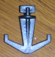
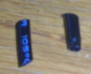
| 001 | Belt hook | 4 + 4 extra | Attach to notches in middle of Belt cover to provide a place to hang belts | Plastic (1); black, hard | 2 | 3.6 x 1.355 x 0.3 | Injection molding | |
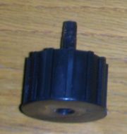
| 002 | Locking screws | 2 | Lock Top assembly into place over closet rod | - | 12 | Cap: 2.4 dia x 1.0
Screw: 0.5 dia x 3.3 | Purchased part | |
| 003 | Top assembly | 1 | Attaches tie rack to closet rod; there is an arrow to indicate the direction which it slides in | Plastic (2); black, hard, finished surface | 26 | 11.57 x 4.5 x 1.9 | Injection molding | |
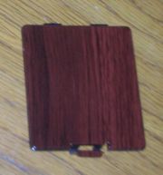
| 004 | Battery cover | 1 | Protects batteries from the environment and keeps them in place | Plastic (2) | 9 | 6.9 x 6.12 x 0.2 | Injection molding | |
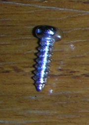
| 005 | Screws | 6+7+2 |
| - | 0.5 | 0.4 dia x 1.18 | Purchased part | |
| 006 | Belt cover | 1 | Holds Rotating belt, Belt gear and Belt rotator to tie rack | Plastic (2) | 45 | 29.5 x 4.6 x 0.9 | Injection molding | |
| 007 | Rotating belt | 1 |
| Plastic (3); black, flexible | 55 | 36.5 x 12.5 x 2.41 | Injection molding (manfuctured as a single part since no visible seams are present) | |
| 008 | Belt gear | 1 |
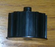
| Plastic (4); black, hard | 14 | 4 dia x 2 x 2.05 (pin) | Injection molding | |
| 009 | Belt rotator | 1 | Holds other end of belt in place and allows for rotation | Plastic (4) | 14 | 4 dia x 2 x 1.7 (pin) | Injection molding | |
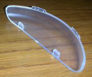
| 010 | Light cover | 1 | Protects Light bulb | Plastic (5); clear, hard | 8 | 3.1 x 10.35 x 1.4 | Injection molding | |
| 011 | Top cover | 1 | Encloses the mechanism that causes rotation | Plastic (2) | 150 | 37.95 x 13.9 x 4.8 | Injection molding | |
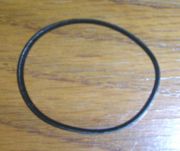
| 012 | Gear belt | 1 | Attaches Magnetic motor to Gear driver | - | 0.5 | 6 circ x 0.2 | Purchased part | |
| 013 | Gear cap | 4 | Holds gears and Gear driver on Pins | - | 0.1 | 0.25 ID x 0.3 OD | Purchased part | |
| 014 | Gear driver | 1 | Attaches Magnetic motor to gear train | Nylon | 2 | 2.3 dia x 1.0 | Injection molding | |
| 015 | Gear, clear | 2 | Decreases speed provided by the Magnetic motor and increases torque | Nylon 6 | 3 | 4.3 dia x 0.8 | Injection molding | |
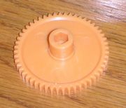
| 016 | Gear, yellow | 1 | Decreases speed provided by the motor and increases torque | Nylon 5 | 3 | 4.3 dia x 1.2, hexagonal core | Injection molding | |
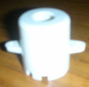
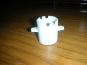
| 017 | Motor cover | 1 | Protects Magnetic motor | Plastic (6); cream, hard | 6 | 2.7 dia x 3.2 | Injection molding | |
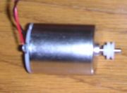
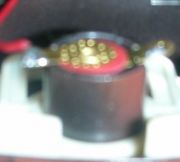
| 018 | Magnetic motor | 1 |
| - | 136 | 2.4 dia x 3.1 | Purchased part | |
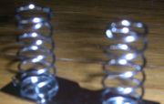
| 019 | Spring | 2 |
| - | 3 | 0.9 dia x 2.4, unloaded | Purchased part | |
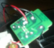
| 020 | Circuit board (with wires) | 1 |
| - | 5 | 3.0 x 3.85 | Purchased part; main unit of subassembly | |
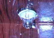
| 021 | Light bulb | 1 |
| - | 2 | 0.9 dia x 0.7 | Purchased part | |
| 022 | Switch | 1 | Allows switching the direction of rotation and activates Light bulb | Plastic (7); cream, hard | 7 | 6.8 x 3.2 x 0.8 | Injection molding | |
| 023 | Bottom cover | 1 | Encloses mechanisms for rotation | Plastic (2) | 162 | 37.95 x 13.9 x 3.3 | Injection Molding | |
| 024 | Pin | 3 | Holds gear fixed onto Bottom cover | - | 1 | 0.2 dia x 1.4 (yellow gear), x 1.85 (white gears) | Purchased part | |
| 025 | Battery end plate | 2 |
| - | 4 | 4.6 x 1.65 | Purchased part | |
| 026 | Lubricant | 1 | Facilitates movement in the gear train | - | 2 | N/A | Purchased part |
