Tolerance analysis
From DDL Wiki
Contents |
Introduction
Manfactured parts are often a conglomerate of basic shapes. While standards are set for specific qualifications in form tolerance analysis, no official methodology exists outlining how to perform such analysis (Samuel et al., 2003). This disparity results in different procedures and techniques for different parts, leading to a possible poor fit and unnecessary scraping of expensive materials. Invasive and non-invasive methods exist for tolerance analysis. This page focuses on contact analysis and one of the primary machines used to do so are Coordinate Measuring Machines (CMMs).
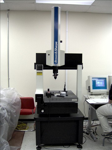
Coordinate Measuring Machine (CMM)
As defined by Busch (1989), coordinate measuring machines (CMMs) locate coordinates on three dimensional structures while simultaneously integrating both the x-y plane and z-plane along with orthogonal relationships. CMMs then utilize a computer and companion software to analyze and interpret measurement results (Dhanish, 2002).
CMMs use 3 axes in order to reach points on a three dimensional surface, with a probe on the third axis. The CMM calculates where a point is in space by reading the displacement of the probe in all the axes and calculating the mathematical offset of the diameter of the tip at every point (DEA 1995 a). There are four different types of CMMs commonly used in industry, each with its own advantages and disadvantages:
1.Gantry Type
2.Cantilever Type
3.Bridge Type
4.Column Type
Use in Industry
CMMs can be used for a variety of projects including:
   * Dimensional measurement
   * Profile measurement
   * Angularity or orientation measurement
   * Depth mapping
   * Digitizing or imaging
   * Shaft measurement
While it is certainly easier to perform such analysis on symmetrical objects, with the correct supporting software(i.e. CAD) irregular shapes can also be studied. Objects with concave features, such a turbine engine casing can provide exceptional challenges. In these cases non-contact (i.e. laser) analysis tools exist, though these are much more expensive.
Advantages
Busch (1989) states that such a device has several advantages in a quality-control setting when combined with certain criteria, such as:
1. Multiple features-when there are several geometric features being controlled
2. High unit cost-if destructive inspection is not viable, then a CMM is the less costly alternative
3. Production interruption-CMM inspection will not cause downtime in machining
Analysis
A cross-combination of fitting algorithm, and sampling method are commonly used to analyze products.
1. Sampling Strategy
There are also a wide variety of sampling strategies to choose from when performing form evaluation. The four most common in industry are random (RND), Hammersley (HM), Halton-Zaremba (HZ), and Aligned Systematic (ALS).
2. Fitting Algorithm
There are many fitting algorithms available to calculate the zone of error, such as downhill simplex, Monte Carlo, nonlinear optimization, 2D curve contours (Qiu et al., 2000) and convex hull (Lai et al., 1996). However, the two fitting algorithms used most extensively in industry are
A. Least-squares (LSQ): a method of finding a center to minimize the objective function
B. Linear optimization (LOPT): minimizes the maximum error between points and a fitted line.
Data from cross studies are commonly used to determine what sampling size, fitting algorithim and sampling method are needed to provide relatively accurate measurements while minimizing cost.
Figure 1 Two-way interaction plot between number of sampling points (8,64,256) and sampling method (Hammersley, Random)
Limitations of CMM
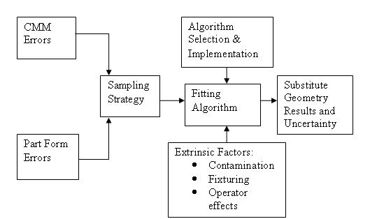
However, Phillips et al. (1998) points out that CMM hardware accumulates error in addition to the error of the object of interest. The researchers generated a schematic illustrating error aggregation in CMM measurement:
Figure 2 explains error aggregation that may occur during data collection.
When evaluating sampling strategies, not only are part errors accumulated but also CMM errors, i.e. failure to calibrate the machine, axis displacement, machine repeatability, etc. Though sampling strategy is intended only to calculate part form error, CMM error is inadvertently calculated as well. The end result is an approximation that incorporates form and CMM errors that cannot be separated.
Wolf et al. (2000) investigated form evaluation using a non-contact (i.e. laser) probes. Wolf et al. points out that contact probes are often time-consuming and are inappropriate for sampling for soft objects. However, due to the extreme expense of non-contact evaluation methods, this method is not viable in general for industrial use.
References & Further Readings
Aguirre-Cruz, J.A. (2003). Inspection of Torus Forms Using Coordinate Metrology. Published Master’s Thesis (Advisor: Dr. S. Raman), University of Oklahoma, Norman, OK.
Aguirre-Cruz, J.A., and Raman, S. (2005). Torus form Inspection Using Coordinate Sampling. Journal of Manufacturing and Engineering Science. 127(1), 84-91.
Badar, M., Raman, S., and Pulat S. (2005). Experimental Verification of Manufacturing Error Patter and its Utilization in Form Tolerance Sampling. International Journal of Machine Tools & Manufacture. 45, 63-73.
Busch (1989). Fundamentals of Dimensional Metrology. New York: Delmar Publishers.
Cebulla, F.M., Midha, S., and Smith, G. (2004). Estimating the Sampling Strategy for Circular Features in Coordinate Metrology. 7th Biennial Conference On Engineering Systems Design and Analysis. 239-245.
Chetwynd, D.G (1979). Roundness Measurement Using Limacon. Precision Engineering, 137-141.
Dhanish, P.B. (2002). A Simple Algorithm for Evaluation of Minimum Zone Circularity Error from Coordinate Data. International Journal of Machine Tools & Manufacture. 42, 1589-1594.
Edgeworth, R.W., and Robert G. (1999). Adaptive Sampling for Coordinate Metrology. Precision Engineering. 23, 144-154.
Huang, J. (1999). An Exact Minimum Zone Solution for Sphericity Evaluation. Computer-Aided Design. 31, 845-853.
Kanada, T., and Suzuki, S. (1993). Evaluation of Minimum Zone Flatness by Means of Nonlinear Optimization Techniques and its Verification. Precision Engineering, 125(4), 736-739.
Kanada, T. (1995). Evaluation of Spherical Form Errors-Computation of Sphericity by Means of Minimum Zone Method and Some Examinations with Using Simulated Data. Precision Engineering. 17, 281-289.
Kurfess, T.R., and Banks, D.L. (1995). Statistical Verification of Conformance to Geometric Tolerance. Computer-Aided Design. 27(5) 353-361.
Lai, J., and Chen, I. (1996). Minimum Zone Evaluation of Circles and Cylinders. International Journal of Machining Tools and Manufacturing. 36(4), 435-451.
Lee, G., Mou, J., and Shen, Y. (1997). Sampling Strategy Design for Dimensional Measurement of Geometric Features Using Coordinate Measuring Machine. International Journal of Machining Tools and Manufacturing. 37(7), 917-934.
Liu, C., Jywe, W., and Chen, C. (2004). Quality Assessment on a Conical Taper Part Based on Minimum Zone Definition Using Genetic Algorithms. International Journal of Machine Tools & Manufacture. 44(2-3), 183-190.
DEA spa A, (1995). TOTUR for Windows: Programming Manual, Code: M1U048EB. Moncaleiri, I.
DEA spa B, (1995). TOTUR for Windows: User’s Guide, Code: M1U038EB. Moncaleiri, I.
Montgomery, D.C (1997). Design and Analysis of Experiments. New York: John Wiley & Sons, Inc.
Montgomery, D.C. (2001). Introduction to Statistical Quality Control. New York: John Wiley & Sons.
Orady, E., Li, S., and Chen, Y. (2000). Evaluation of Minimum Zone Straightness by a Nonlinear Optimization Technique. Journal of Manufacturing Science and Engineering. 122, 797-797.
Phillips, S.D., Borchardt, B., Estler, W.T., and Buttress, J. (1998). Estimation of Measurement Uncertainty of Small Circular Features Measured by CMMs. Precision Engineering. 22, 87-97.
Prakasvudhisran, C. (2002). Dimensional Measurement of Conical Features Using Coordinate Metrology. Published Ph.D Dissertation (Advisor Dr. S. Raman), University of Oklahoma, Norman, OK.
Prakasvudhisran, C., and Raman, S. (2004). Framework for Cone Feature Measurement Using CMM. Journal of Manufacturing and Engineering Science. 126, 169-177.
Ravindran, A., Phillips, D.T., and Solberg, J.J. (1987) Operations research: Principles and practice (2nd Ed.). New York: John Wiley & Sons, Inc.
Samuel, G.C., and Shummugam, H.S. (2003). Evaluation of Sphericity Error from Form Data Using Computational Geometric Techniques. International Journal of Machine Tools & Manufacture. 42(3), 405-416.
Wolf, K., Roller, D., and Schafer, D. (2000). An Approach to Computer-Aided Quality Control Based on 3-D Coordinate Metrology. Journal of Materials Processing Technology. 107, 96-110.
Qiu, H., Cheng, K., Li, Y., Li, Y., and Wang, J. (2000). An Approach to Form Deviation Evaluation for CMM Measurement of 2D Curve Contours. Journal of Materials Processing Technology. 107, 119-126.
Yau, H., and Menq, C. (1996). A Unified Least-Squares Approach to the Evaluation of Geometric Errors Using Discrete Measurement Data. International Journal of Manufacturing Tools. 36(11), 1269-1290.
http://en.wikipedia.org/wiki/Coordinate-measuring_machine
Page added by Allison Chioma Oguh, Erica Delores Pratt, Chia-Pei Denise Hsu (Fall 2007)


