Bicycle drivetrain
From DDL Wiki
Contents |
Executive Summary
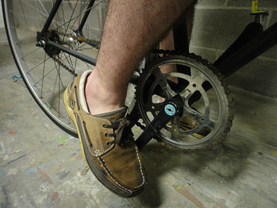
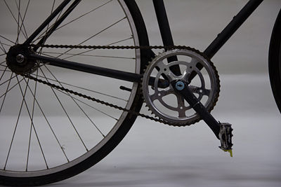
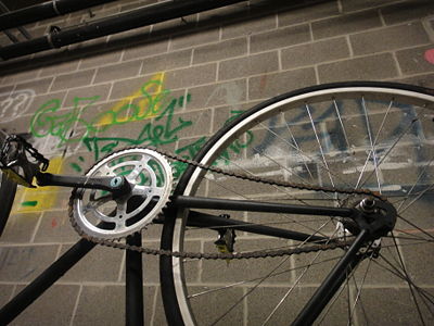
To optimize the design of a chain tensioning device (be in powered by human power or an external source), the first step was to dissect the use of an existing application. A single, fixed-gear bicycle was acquired and dissected; areas of improvement were addressed via DFMA, FMEA and DFE.
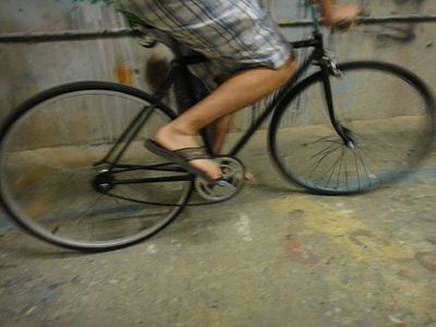
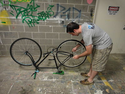
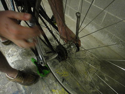
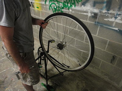
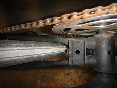
Results from the product usage and evaluation study had proven that the system was not only incredibly non-intuitive, but required far too many specific tools to work on in an emergency situation. Though the subject was technically inclined, results from an attempt tot tighten the chain were incredibly poor and could easily result in injury. Even when this task was completed successfully, the tire was crooked, another opportunity for injury.
Results from the DFMA analysis... [BRIAN]
From the FMEA analysis... [ADAM]
From the DFE analysis... [ANNE]
Thus, the existing product was found to have quite a few issues. It is the goal of this team to improve the existing design as well as possible within the budgetary restrictions. Subsequent analysis will investigate these points further and determine possible design solutions.
Primary Stakeholders and Product Needs
The primary stakeholders in this supply chain are the Manufacturers, the bike shops who will retail this and the bike riding consumer.
Consumers:
Consumers are the target audience who purchases the product, these people would most likely own one or more single speed road bikes and may or may not be hipsters (but probably)
- Ease of use for both alignment and tensioning of the rear wheel
- Robust construction for reliable road use
- Low weight because this is a human powered vehicle
- Lowest possible cost for a quality product
- Ease of maintenance
- Compatible with many bike frame designs, IE not a custom part for each frame
- Easily installed on bikes not currently using it
- Weather resistance
Retailers:
These are the people and companies that would sell the product to the consumers
Most likely this would be from specialized bike shops (IE iron city bikes)
- Small size for easy storage
- Universal compatibility use so they do not have to stock more than a couple sized/configurations
- Ease of maintenance
- Low price
Manufacturers:
Manufacturers create the product for sale and effects on time and pricing impact the entire supply chain.
- Time to manufacture is important and all custom machined parts slow down the process
- Cost to manufacture and of materials; exotic materials would not be good here.
Product Function and Evaluation
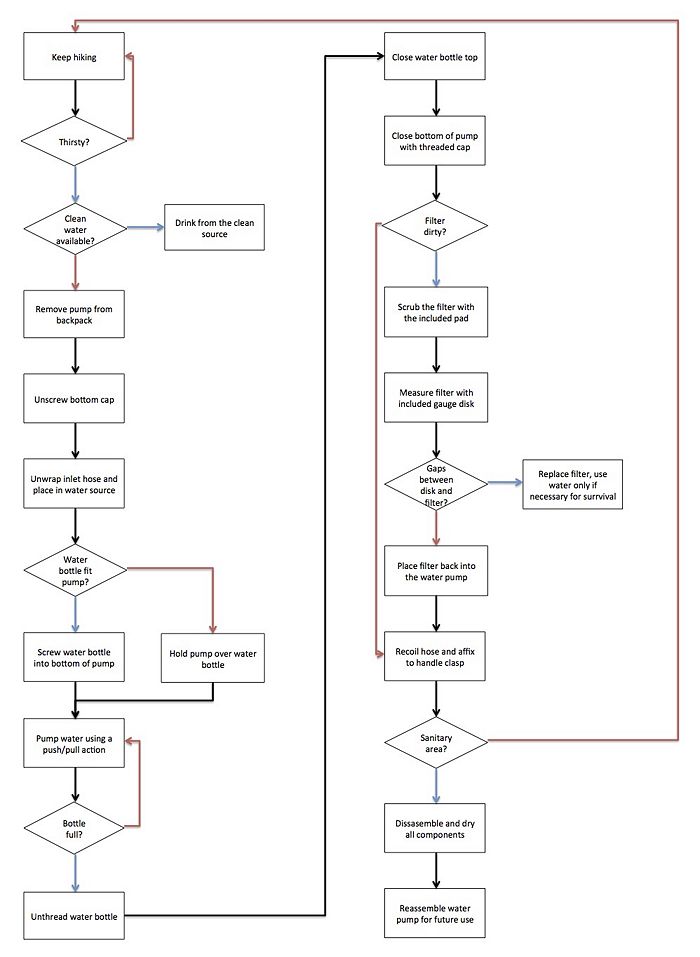
The MSR MiniWorks Pump operates via an oscillating piston with two one-way valves. A duck valve is inline with the pump head and housing to prevent excessive pressure buildup in the housing. The entire product can be completely dismantled in-field, and can be maintained with little prior knowledge. The design seems very simple yet efficient in its purpose.
Usage
Find the cleanest possible source of water. The intake hose is unwound, and then the intake hose is inserted into the water source. Attach the pump to the water container. Pump water at a steady rate, until container is full. Pull the intake hose out of the water, and pump to clear pump of any additional water.
Mechanical Function
The product contains a lever that is attached to an oscillating piston with two check valves. On the intake stroke, the intake check valve allows water to travel through the water source into the piston. On the compression stroke, the intake check valve is closed and the bottom check valve allows water to be forced through the filter chamber. The filtered water is then sent out of the pump. A duck valve lies between the pump head and housing to prevent a buildup of pressure. If the input flow is greater than the outlet flow, then the spring on the duck valve will compress and pressure will be released.
Preliminary User Study
Our group conducted a preliminary user study and determined that the product was self explanatory for either experienced hikers or anyone with moderate technical know-how (i.e. CMU engineering majors). Our group was able to completely dismantle the product without the use of any tools and easily discern the purpose of each part. This product would only need to be purchased by someone with a lot of experience in hiking and the outdoors, as someone without this experience should not be taking trips during which they won't have access to drinkable water. Therefore, nobody should be using it without any prior knowledge.
There are many well-thought-out features which exhibit themselves through simple use. First off, the outlet of the pump is threaded the same size as a Nalgene bottle, so that the pump can sit directly on the bottle and there is no risk of contamination. The included cap for the outlet of the pump also serves to reduce contamination when not in use. The rubber hosing wraps around the pump housing and is secured by a small c clamp in the handle. This serves to not only hold the handle down when when not in use (and prevent incidental breaking), but the c-clamp is properly sized so that it squeezes the hosing closed to prevent excess contamination. Finally the handle is contoured to fit well with the averaged sized in a comfortable pumping position.
Not many issues arise when using the MSR water pump. The most notable problem lies in the fact that the pumping action is cramped and requires several minutes to fill a hiking-sized water bottle. If there were a way to reduce the pumping effort required while keeping the small footprint of the product, it would probably be very beneficial. The only other foreseeable issues are broken parts or a clogged filter, which we didn't encounter and couldn't simulate during this study.
List of Parts
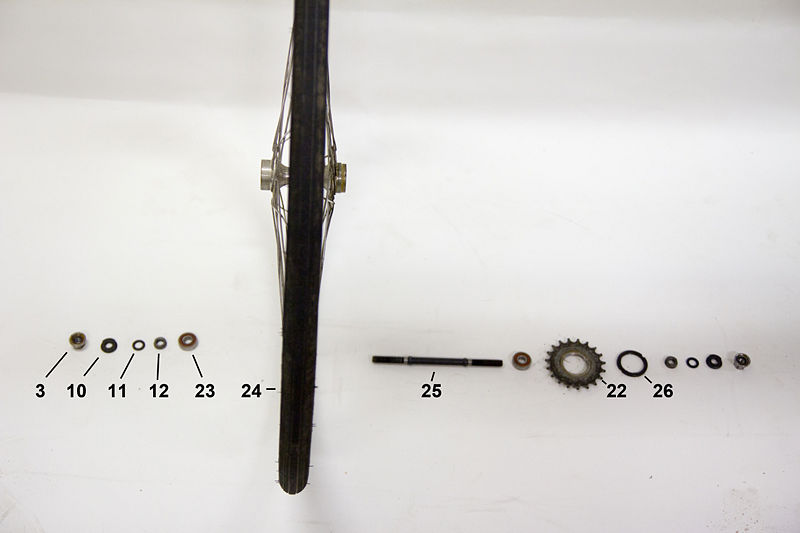
The following details the list of parts of a fixed gear bicycle tensioner and drivetrain.
Parts list table
| Part Number | Name | Quantity | Mass (g) | Subassembly | Function | Material | Manufacturing Process/ Purchased Component | Image |
|---|---|---|---|---|---|---|---|---|
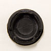
| 1 | Dustcaps | 2 | <1 | Crank Assembly | Keep dirt out of bottom bracket | Plastic | Injection Molding | |
| 2 | Lock nuts | 2 | 6 | Crank Assembly | Retainment/Assembly | Steel | Catalog Purchase | |
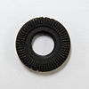
| 3 | Nut w/ integrated lock washer | 2 | 16 | Crank Assembly | Retainment/Assembly | Steel | Catalog Purchase | |
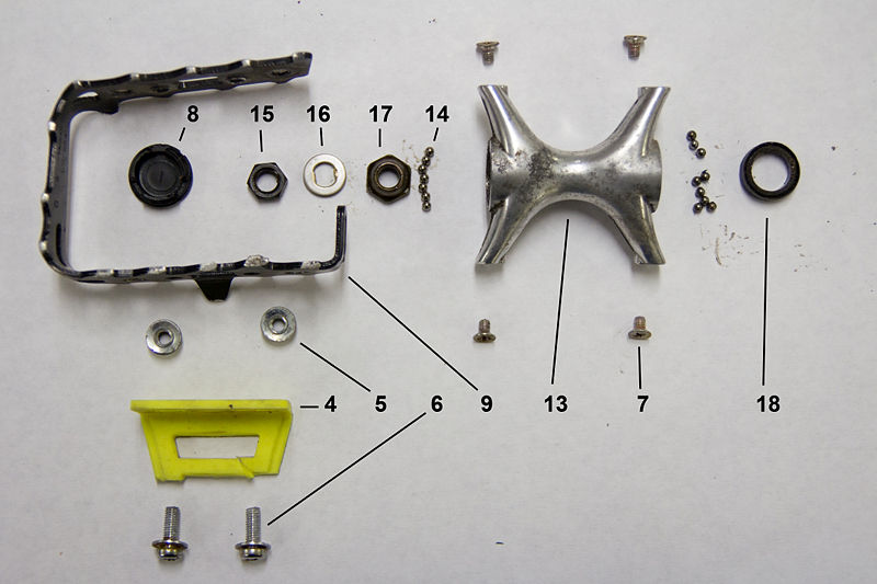
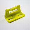
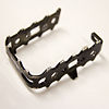
| 4 | Toe strap holders | 2 | 6 | Pedals | Ability to secure toe | Plastic | Injection Molding | |
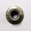
| 5 | Flange nut | 4 | <1 | Pedals | Attach toe strap holder to foot grip | Steel | Catalog Purchase | |
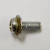
| 6 | Screw w/ integrated washer | 4 | <1 | Pedals | Attach toe strap holder to foot grip | Steel | Catalog Purchase | |
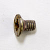
| 7 | Screw | 8 | <1 | Pedals | Attach foot grip to pedal | Steel | Catalog Purchase | |
| 8 | Pedal cap | 2 | <1 | Pedals | Keep dirt out of pedals | Plastic | Injection Molding | |
| 9 | Foot grip | 2 | 27 | Pedals | Prevent foot from slipping off pedal | Aluminum | Die Casting | |
| 10 | Outer jam nut | 2 | 9 | Sprocket Assembly | Retainment/Assembly | Steel | Catalog Purchase | |
| 11 | Washer | 2 | <1 | Sprocket Assembly | Retainment/Assembly | Steel | Catalog Purchase | |
| 12 | Inner jam nut | 2 | 7 | Sprocket Assembly | Retainment/Assembly | Steel | Catalog Purchase | |
| 13 | Pedal | 2 | 54 | Pedals | Central Component in Pedals | Aluminum | Die Casting | |
| 14 | Ball bearings | 24 | <1 | Pedals | Friction Prevention | Steel | Catalog Purchase | |
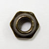
| 15 | Nut | 2 | 3 | Pedals | Retainment/Assembly | Steel | Catalog Purchase | |
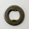
| 16 | Double D Washer | 2 | <1 | Pedals | Catalog Purchase | Steel | Catalog Purchase | |
| 17 | Nut w/ seat for ball bearings | 2 | 5 | Pedals | Retainment/Assembly | Steel | Catalog Purchase | |
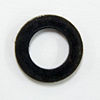
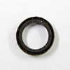
| 18 | O-ring | 2 | <1 | Pedals | Keeping lubricants inside pedal | Rubber | Catalog Purchase | |
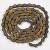
| 19 | Chain | 1 | 304 | Drivetrain | Drive rear sprocket using rotation of front sprocket | Steel | Stamping and Pressing | |
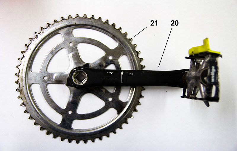
| 20 | Crank | 1 | 260 | Spindle/Crank Assembly | ? | Steel, aluminum | Die Casting | |
| 21 | Crank w/ sprocket | 1 | 626 | Spindle/Crank Assembly | ? | Steel | Assembly - Stamping and Die Casting | |
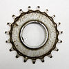
| 22 | Rear sprocket | 1 | 82 | Rear Hub Assembly | ? | Steel | Stamping with Post Machining | |
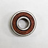
| 23 | Bearing | 2 | 19 | Rear Hub Assembly | ? | ? | Catalog Purchase | |
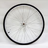
| 24 | Rear wheel | 1 | ? | Rear Hub Assembly | ? | Steel, Rubber, Aluminum | Assembly - Catalog Components Mated with a CNC lathed hub | |
| 25 | Rear axle | 1 | 101 | Rear Hub Assembly | ? | Steel | CNC Lathing | |
| 26 | Sprocket retaining ring | 1 | 15 | Rear Hub Assembly | ? | Steel | Catalog Purchase | |
| 27 | Ball bearings | 2 | 14 | Spindle/Crank Assembly | Countering Friction in Pedals | Steel | Catalog Purchase | |
| 28 | Left threaded cap | 1 | 54 | Spindle/Crank Assembly | Retainment/Assembly | Steel | Catalog Purchase | |
| 29 | Spindle | 1 | 209 | Spindle/Crank Assembly | Allow wheel to move | Steel | CNC Lathing | |
| 30 | Right threaded cap | 1 | 47 | Spindle/Crank Assembly | Retainment/Assembly | Steel | Catalog Purchase | |
| 31 | Crank Spacer | 1 | 47 | Spindle/Crank Assembly | Retainment/Assembly | Steel | Stamping |
Design For Manufacturing and Assembly
Design For Manufacturing [DFM]
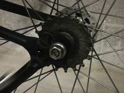
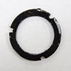
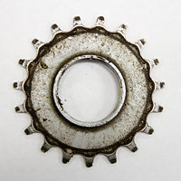
Dissection of the fixed gear drive train revealed several areas for improvement. The majority of the drive train consists of cast or stamped steel and aluminum components which allows for a high volume of relatively cheap parts to be made. High tolerance components such as the rear axle, hub and spindle are likely CNC lathed in order to achieve required tolerances for bearing surfaces. Unfortunately this drastically increases the time and money spent to produce such parts. However, considering the cost of machining the rear hub it is multifunctional: it locates the bearings, provides torque transfer and mounting for the sprocket and secures the wheel. It should be noted some components of the pedal assembly (dust cap, toe strap holders) are injection molded plastic, allowing for very cheap manufacture after initial mold investment. Interestingly, it seems the use of injection molded plastic for other applications such as the pedal and pedal grip could be a viable option at the expense of some durability. Furthermore, standardizing bearings between the pedal set, crank assembly and hub could reduce costs and increase the feasibility of injection molding the pedal set. Other notable components include the rear hub, sprocket and retaining ring and their method of interface. The hub uses a stepped threaded area in order to accommodate the larger diameter sprocket and smaller diameter retaining ring. This setup increases manufacture time and cost by requiring two separate sized threads to be machined onto the hub as well as a lip machined into the sprocket for the retaining ring to seat against. Instead a single diameter thread may be used along with a locking nut. A similar oversight occurs in the pedals where ball bearings are retained by a special nut and jam nut instead of a single bearing set and lock nut assembly.
Overall the materials and production methods provide a durable, well finished system but certainly leave room for improvement. By minimizing part count, standardizing components and design features and simplifying parts it should be possible to reduce the production cost by a fair margin.
DFM Summary
- The drive train is made of durable, aesthetic pieces at the expense of production cost.
- Casting and stamped processes are used where applicable to reduce high-volume cost.
- The drive train uses many non-standardized parts across the system.
- Some components are excessively complicated or superfluous for their function
Design for Assembly [DFA]
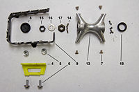
Dissection of the fixed gear drive train show inconveniences that negatively affect assembly time, assembly worker training and labor cost. It is likely several of these inconveniences are a result of the fact that assembly is completed by the customer as well as standard bike specific tooling. An experienced user is required to install the drive train assembly correctly as there are many components with no clear assembly order, especially in the bearings for the pedals. Additionally parts must be installed from several directions and access is often obstructed if the system is assembled in the incorrect order. For example, there is no feature in the pedal grip to allow for pedal removal. Instead, it is necessary to remove the pedal grip to gain access to the nut for pedal removal. This may be easily remedied through a clearance hole in the pedal grip. Additionally, the use of unnecessarily thin retaining rings and sprocket requires 2 special bike wrenches which are significantly thinner than standard wrenches. While this is relatively standard in the biking industry for enthusiasts or shops, it certainly inconveniences an average user looking to conduct maintenance or repair. Also, special care is required when installing the pedal bearing set as it is made up of many individual parts and requires specific assembly order. Tens of ball bearings must be installed, followed by a custom nut requiring specific orientation, a washer and lastly a jam nut. This is a mistake prone assembly and also requires quite some time to install due to the many separate components. There are, however, some well thought out components which ease assembly. For example, the pedal grip uses slots for mounting which maximizes installation compliance, even in the event of a warped or damaged grip assembly. Also, integrated washer/nuts are used to hold the wheel to the frame, minimizing the number of fasteners on a part which is likely removed often.
While there are some positive points for the drive train assembly there are still numerous ways to improve upon installation simplicity and time. We believe there may have been a lesser focus on design for assembly due to the fact that these components are often assembled by the customer. As such the manufacturing company realizes no lost revenue (other than customer backlash) due to the relatively inefficient design.
DFA Summary
- The designers likely did not prioritize installation simplicity or speed.
- Special tools are required for proper assembly.
- The installation process is mistake prone and requires a fair amount of experience.
Failure Mode and Effect Analysis [FMEA] [ADAM]
Design for Environment [ANNE]
Team Members
Michael Ornstein - Team Leader
Rob Wojno - Product Function, Evaluation and Usage Study
Anne Dirkes - DFE
Brian Langone - DFMA
Adam Brecher - FMEA
Each member of the team expressed interest in their assigned field; work is done on a regular basis with Mr. Ornstein overlooking the direction and making sure it's in line with expectations.
References
Cascade Designs, Inc. MSR MiniWorks EX Water Filter. 24 Jan. 2012. Instruction Manual. Seattle, WA.
Carnegie Mellon University Green Design Institute. (2008) Economic Input-Output Life Cycle Assessment (EIO-LCA), US 1997 Industry Benchmark model [Internet], Available from:<http://www.eiolca.net> Accessed 23 September, 2012.
Dieter, George E., and Linda C. Schmidt. Engineering Design. 4th Edition. New York, NY: McGraw-Hill, 2009. 707-715. Print.
"MSR® MiniWorks™ EX Microfilter Schematic." MSR. Cascade Designs, Inc. Web. 12 Feb. 2012. <http://cascadedesigns.com/msr/water-treatment-and-hydration/expedition-water-treatment-and-hydration/miniworks-ex-microfilter/product>.
