Drink cooler
From DDL Wiki
Contents |
Executive Summary
Identification of Stakeholders
End User
This is the person who will ultimately use the product. They will own and operate the product at social occasions. They want to be proud of their purchase, and enjoy the experience of using the product. The things they will look for in the product:
- Enhances ability to host events
- Short duty cycle
- Ease of operation
- Ease of setup
- Ease of cleanup
- Can operate unattended
- Liked by guests
- Cheap
- Ease of storage
- Works on arrival
- Safe
- Little or no maintenance
- Appearance fits setting
- Attractive exterior
- Does not require additional materials to operate
User’s Associations
The family, friends, co-workers, clients, and other guests whom the user is entertaining. They don’t want the product to interfere with their enjoyment of the event and they want cold beverages at all times. The things they will look for in the product:
- Does not take up space
- Low noise level
- Frees host to entertain
- Short duty cycle
- Hard to accidentally break
- Can be operated while intoxicated
Retailer
The retailer stocks and sells the product, most likely online. They want a product which customers will buy and enjoy using. The things they will look for in the product:
- Return on investment
- Easy to stock
- Inexpensive to ship
- Easy to market online
- Product experience is consistent
Marketing
The marketing staff of the company which produces the product. They have to get a retailer to stock their product. They also promote the product to increase awareness among potential customers. They are interested in maximizing profits for their company and increasing market share. The things they will look for in the product:
- Fits with brand image
- Improves brand image
- Low barriers to market entry
- Easily identifiable market
- Advantages over competitors’ products
- Easy to identify positive features
- Low potential for misuse
- Low potential for litigation
Shipping
The transportation contractors who move product from manufacturing plant to retailer’s warehouse, and from retailer to end user. They want a product which is easy to pack in large quantities, and presents no hazards to the person transporting the product. The things they will look for in the product:
- High packing factor
- Robust packaging
- Low weight-to-volume
- Low potential for damage during transit
- Low environmental needs during transit
- Not hazardous to driver
- Easy to load and unload
Product Usage
Description of Use and Mechanical Functioning
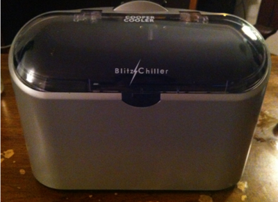
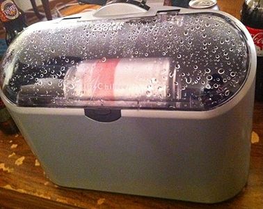
The product, the Blitz Chiller, operates in the most general sense, by spraying chilled water over a rapidly rotating bottle or can. The goal of this is to quickly cool a beverage by inducing forced convective heat transfer using 0°C water to cause a rapid temperature decrease.
1)To operate the unit, must first be plugged into a wall socket. A push button latch on the front of the machine allows the user to unlatch and open the lid of the machine.
2)Once the machine is plugged in and opened, a tray of ice cubes (approximately 16 standard sized ice cubes) is placed in the ice-water bin of the machine.
3)One and half cups (12 oz) of cold water are the added to the ice-water bin creating an ice water bath in the bottom of the machine. The ice-water bath does not cover or touch the area where the beverage will sit. The maximum water level is approximately 1-2 cm below the beverage.
4)After the ice-water bath has been set up, the beverage is placed on to the drive roller in the machine and the latch is closed.
5)The user then uses a timer lever on the top of the machine to cool the beverage for 2, 4, or 6 minutes. Once the lid is completely closed on the machine (a specific safety feature) and the timer lever has been set, the machine begins to operate.
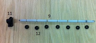
The driver roller is a long metal shaft that runs the length of the ice-water bin and is covered in rubber rings. These rubber rings ensure good contact between the driver roller and the beverage so that as the driver roller spins, the drink will spin with it.
As the machine operates, the driver roller spins causing the beverage to spin quickly. Cold water is drawn from the bottom of the ice water through a small drain and is sprayed over the rotating beverage through an opening in the upper middle section of the ice-water bin located above the beverage. Once the selected amount of time has elapsed, both the driver roller and the cold water spray stop.
6)The lid may then be opened using the latch and the beverage removed and enjoyed.
7) Once several beverages have been cooled, more ice may be needed to refill the ice-water bin, so water in the bin may be emptied from the top of the machine to make room for more ice.
Results of User Studies
The product was found to be a robust, attractive design, and very easy to use. Initial studies found that company claims about temperature changes for a given container and chill time were supported (Blitz Chiller). The product also lived up to claims that it would not make the beverages foamy or alter their flavor (Blitz Chiller). After a few uses, it was observed that bottles were making gouges in the end of the reservoir.
Bill of Materials
Assembly List
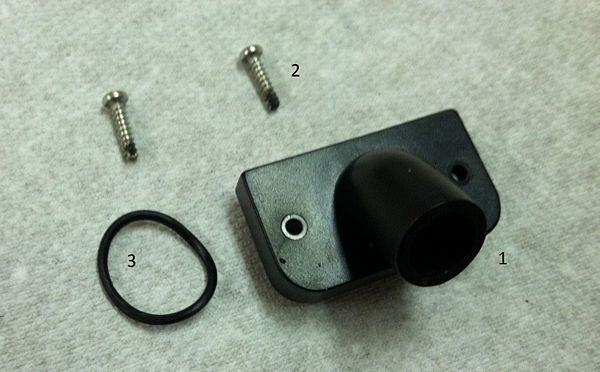
Water Spout Assembly:
Bottom Assembly:
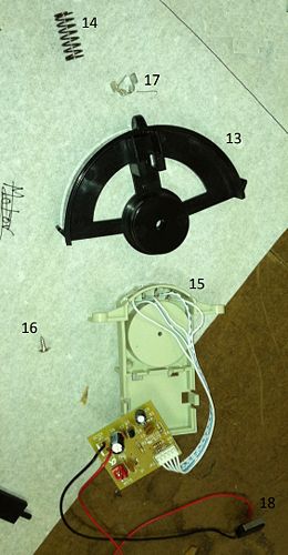
Rotary Bar Assembly:
Circuitry Assembly:
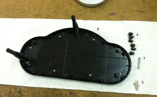
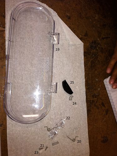
Lid Assembly:
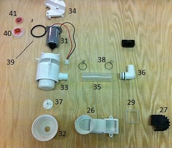
Bottom Drain and Motor Assembly:
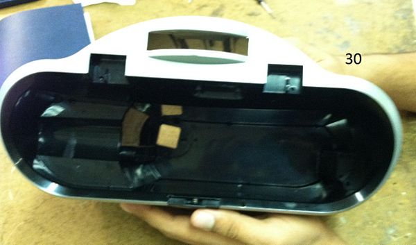
Entire Housing Assembly:
Parts List
Design for Manufacturing and Assembly
The competitor's drink cooler was analyzed to determine strengths and weaknesses with their design pertaining to ease of manufacturing and assembly. Overall, competitor product seemed to be well-designed in these two areas. However, there were a few areas that leave room for improvement.
Manufacturing
The biggest success of the competitor drink cooler was the design of the motor. One motor was designed that played a multifunctional role as it powered both the water pump and also the drink rotator. This was critical to the design as it allowed the entire product to be both compact and cheap. We had anticipated having two separate motor for each of those roles. All parts in the design beyond those that would be specific to this product were standardized. The only custom parts were found to be the external housing, rotator bar, motor housing, and water plumbing. Among these the motor housing and rotator bar were designed such that they could also be used across other drink cooler models produced by this same company, increasing scale of production while reducing required equipment. The standardized components used in the design were the screws, springs, motor, pulley, circuit board, and O-rings. This took advantage of the scale of production. In addition, it was designed such that only one drill size was needed and all the holes could be drilled from as few positions as possible.
The only two areas weaknesses were the mechanical control system and the low construction tolerances. The control system featured several parts that had to be fitted together in a precise way. Still, the control system was very sluggish and left room for improvement. A toggle system might be a potential way to improve the design. The tolerances of the entire system were very small. This was necessary because the system needs to be water tight. This is a weakness, but will also be hard to improve on.
Assembly
The design was made in a way to ease assembly. A majority of the pieces fit into the external housing in order from bottom to top. In addition, most of the parts are press fit. These parts were designed to be round with guides. This allows for easy insertion that will snap into the correct position. These press fits also reduced the requirement for screws, which are tedious and would complicate the assembly. In addition, the water plumbing was joined with a flexible rubber connector. This improved the tolerances of the tubing. Finally, the custom parts were injection molded using two materials. One of for the external housing and one for the interior parts.
The only weakness identified was with the choice of fasteners in some cases. There is one connection created using hot glue that joins the water tubing to the inside wall of the external housing. This was likely done to reduce vibrations. However, this one connection requires the use of a completely new tool. Finding a way to eliminate the hot glue connection with either a screw or a press fit would reduce the number of tools required. This would also save time in assembly. The other weakness was that some of the screws were hard to reach. Their insertion points were at the very bottom external housing. Reaching to these locations to screw them in is inefficient. A potential solution is to either replace them with press fits or relocate the screws such that they are in a more accessible position.
Failure Mode and Effects Analysis
Table is written, needs to be uploaded. Will be completed by tonight.
| Item & Function | Failure Mode | Effects of Failure | S | Causes of Failure | O | Design Controls | D | RPN | Recommended Actions |
|---|---|---|---|---|---|---|---|---|---|
| Motor | Burnout | Reduced or no motor output | S | Heat, excess voltage | O | Voltage Input Regulator | D | RPN | None |
Design for Environment
When we tried to compute the impact the product had on the environment over the course of its lifetime we considered the material extraction, production, use, end of life, and transportation of the product. We did a green house gas impact analysis using the EIOLCA tool separately for its production aspect and the use aspect of the product.
Production
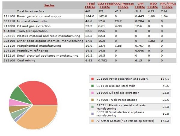
For the production section since the product is mostly made up of plastic barring the fasteners, motor and electronic equipment we used the sector Small Appliances Manufacturing(335210) since we felt none of the standard ones in the model fit our product. Given that one product costs about $40 at retail in 2002 its purchases price would have been $34 approximately. Running the model for this sector we found that for every $1 million spent on manufacturing the plastic product 1.94 metric tonnes of CO2 were released. The break up for each sector is below. Scaling this down for $34 we found that through the life cycle of this product it uses 0.0000656 metric tonnes of CO2 which @$30 tax a metric ton works out to be $0.0197. Hence clearly the greenhouse gases emitted when manufacturing the product is very insignificant.
Use
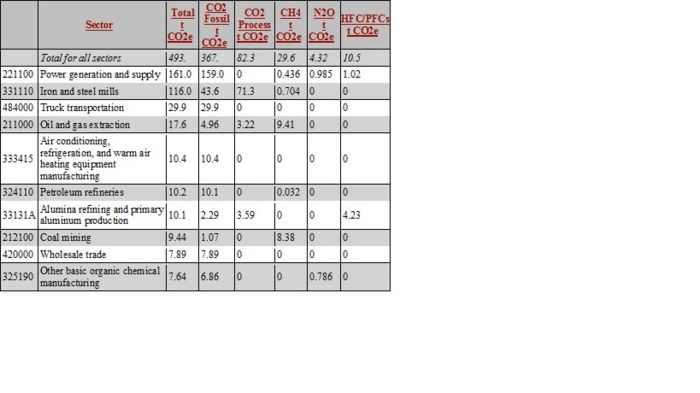
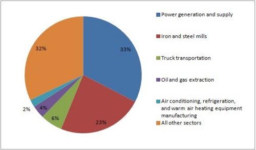
Our product uses a lot of ice which is used to cool the beverage down to the required temperature. During the user study we found that one tray of ice cools about 2 cans effectively before warming up to not useable degree. Hence over a lifetime of the product we estimate it using 1000 trays of ice. Hence this is a significant amount of ice to be made using refrigeration. For the production of ice we analysed the sector Air Conditioning, Refrigeration and warm air heating equipment and the results were as follows in the table and graphs below. Using the cost of ice at Giant Eagle we estimated that one tray of ice costs 50 cents. Hence we will use $500 of ice over the lifetime of the product. Based on that fact that 493 mt CO2 are released for $100000 for $500 the product uses 0.2465 mt CO2¬ and at a tax of $30 per mt CO2 it worked out to be a significant amount of $7.395.
Overall Analysis and Conclusions
The carbon dioxide tax would make a significant impact on the cost of the product. The highest contributor to the tax is power generation and supply which contributes over 32% of the emissions with other sectors as iron and steel mills contributing 21%. However other than these two sectors all other sectors contributed less than 5% of overall emissions. We found that the overall tax on the product due to CO2 emissions was fairly significant mostly due to the production of ice. The using of ice contributes to 99% of the environmental impact the product has. Hence for the next steps of our project we will like to increase the thermal efficiency of the product and reduce the amount of ice while cooling. Ice being the contributor to the most environmental impact was consistent with our hypothesis.
Team Member Roles
Phase I team roles
- Team Leader - Dhruv Swaroop
- DFMA Leader - Ojas Mainkar
- FMEA Leader - Robert White
- DFE Leader - Arvin Sabu Joseph
- Presentation Leader - Charlie Munoz
References
- "Blitz Chiller." Blitz Chiller. Web. 10 Feb. 2012. <http://www.blitzchiller.com/>.
