Iron
From DDL Wiki
Contents |
Executive Summary
Lorem ipsum dolor sit amet, consectetur adipiscing elit. Ut elementum elit vel tortor scelerisque auctor. Donec urna dui, eleifend eget adipiscing vulputate, feugiat id nisl. Donec mattis, quam in tincidunt ullamcorper, orci tellus condimentum dui, aliquet faucibus risus nunc et nunc. Vestibulum metus justo, volutpat sed consequat eget, mollis sed neque. Maecenas dignissim hendrerit malesuada. Aliquam dictum gravida orci ut rutrum. Fusce eros lectus, accumsan sed rhoncus eu, tempor sed magna. In ac lacus urna, ut cursus nisl. Curabitur ac dui nisl, in imperdiet orci. Aliquam quam dui, tincidunt quis volutpat quis, convallis a ipsum. Suspendisse quis molestie lorem. Nunc vel magna commodo nunc viverra tempor id blandit neque. Donec nec elementum ligula. Cras accumsan, urna eget dictum varius, arcu nunc porttitor tortor, sit amet feugiat nisl elit vitae elit. Proin eget tellus lectus, tempus tincidunt augue. Sed sagittis iaculis orci, sit amet tempus dui tincidunt in.
Product Stakeholders
Stakeholders Major stake holders for our product would include: dry cleaners, home cleaning services, busy mothers, iron manufactures such as Black & Decker and Sunbeam, and major department stores.
| Stakeholder Needs | |||
|---|---|---|---|
| Stakeholder | Consumer | Needs | Wants |
| Consumers |
|
|
|
| Retailers |
|
|
|
| Manufacturer |
|
|
|
| Transportation and Shipping |
|
|
|
Product Use Study
Lorem ipsum dolor sit amet, consectetur adipiscing elit. Ut elementum elit vel tortor scelerisque auctor. Donec urna dui, eleifend eget adipiscing vulputate, feugiat id nisl. Donec mattis, quam in tincidunt ullamcorper, orci tellus condimentum dui, aliquet faucibus risus nunc et nunc. Vestibulum metus justo, volutpat sed consequat eget, mollis sed neque. Maecenas dignissim hendrerit malesuada. Aliquam dictum gravida orci ut rutrum. Fusce eros lectus, accumsan sed rhoncus eu, tempor sed magna. In ac lacus urna, ut cursus nisl. Curabitur ac dui nisl, in imperdiet orci. Aliquam quam dui, tincidunt quis volutpat quis, convallis a ipsum. Suspendisse quis molestie lorem. Nunc vel magna commodo nunc viverra tempor id blandit neque. Donec nec elementum ligula. Cras accumsan, urna eget dictum varius, arcu nunc porttitor tortor, sit amet feugiat nisl elit vitae elit. Proin eget tellus lectus, tempus tincidunt augue. Sed sagittis iaculis orci, sit amet tempus dui tincidunt in.
Product Mechanical Function
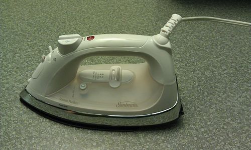
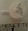
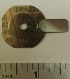
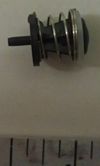
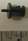
An average iron uses a lot of mechanical systems to heat up the iron base plate. The particular iron we dissected revealed three main mechanical systems. The first mechanism is the steam mechanism which utilizes pump and a compression spring. When the steam button is pressed a pressure gradient is created and the water is pushed up and out into a tube that leads to a drip nozzle. The second mechanism is the temperature sensor control. This is mechanism uses a FPA223-80 temperature sensor that expands and flips a switch when the temperature reaches just over the boiling point. The switch gets flipped and pushes on the bottom of the drip nozzle. On top of the drip nozzle is a compressive spring that get compressed which allows for water from the steam tube to flow down into base plate. Therefore when the temperature of the plate surpasses the boiling point the water from the steam tube is allowed to move toward the hot iron plate to get vaporized. The clean button mechanism works in a similar fashion except the compression spring has a different stiffness so that all the water in the water reservoir is allowed to flow out. The third mechanism is the temperature control/selector mechanism utilized in fabrics selection. The temperature is modified by changing the resistance in the heating mechanism. This is accomplished when the user picks a fabric by using the slider that moves horizontally. Underneath the slider is a circular attachment that converts the translational motion into rotational motion. This rotational movement rotates the resistance modifier mechanism which will either add or subtract resistance to the depending on whether it need to get hotter (add resistance) or colder (subtract resistance). Another basic mechanism that this iron uses is a reset feature. This reset features uses a button pressing mechanism that resets the circuit that controls the power of the heating element. When the reset button is pressed a pin hits the circuit and which resets the power to the heating element.
Assembly
Lorem ipsum dolor sit amet, consectetur adipiscing elit. Ut elementum elit vel tortor scelerisque auctor. Donec urna dui, eleifend eget adipiscing vulputate, feugiat id nisl. Donec mattis, quam in tincidunt ullamcorper, orci tellus condimentum dui, aliquet faucibus risus nunc et nunc. Vestibulum metus justo, volutpat sed consequat eget, mollis sed neque. Maecenas dignissim hendrerit malesuada. Aliquam dictum gravida orci ut rutrum. Fusce eros lectus, accumsan sed rhoncus eu, tempor sed magna. In ac lacus urna, ut cursus nisl. Curabitur ac dui nisl, in imperdiet orci. Aliquam quam dui, tincidunt quis volutpat quis, convallis a ipsum. Suspendisse quis molestie lorem. Nunc vel magna commodo nunc viverra tempor id blandit neque. Donec nec elementum ligula. Cras accumsan, urna eget dictum varius, arcu nunc porttitor tortor, sit amet feugiat nisl elit vitae elit. Proin eget tellus lectus, tempus tincidunt augue. Sed sagittis iaculis orci, sit amet tempus dui tincidunt in.
Sub-Assembly
Lorem ipsum dolor sit amet, consectetur adipiscing elit. Ut elementum elit vel tortor scelerisque auctor. Donec urna dui, eleifend eget adipiscing vulputate, feugiat id nisl. Donec mattis, quam in tincidunt ullamcorper, orci tellus condimentum dui, aliquet faucibus risus nunc et nunc. Vestibulum metus justo, volutpat sed consequat eget, mollis sed neque. Maecenas dignissim hendrerit malesuada. Aliquam dictum gravida orci ut rutrum. Fusce eros lectus, accumsan sed rhoncus eu, tempor sed magna. In ac lacus urna, ut cursus nisl. Curabitur ac dui nisl, in imperdiet orci. Aliquam quam dui, tincidunt quis volutpat quis, convallis a ipsum. Suspendisse quis molestie lorem. Nunc vel magna commodo nunc viverra tempor id blandit neque. Donec nec elementum ligula. Cras accumsan, urna eget dictum varius, arcu nunc porttitor tortor, sit amet feugiat nisl elit vitae elit. Proin eget tellus lectus, tempus tincidunt augue. Sed sagittis iaculis orci, sit amet tempus dui tincidunt in.
Bill of Materials
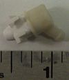
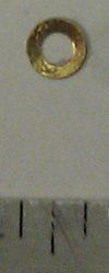
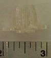
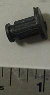
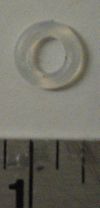
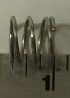
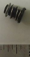
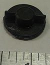
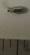
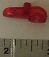
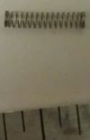
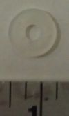
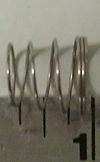
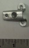
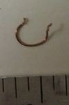
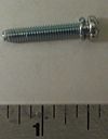
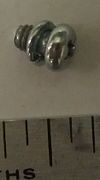
The following is a table of individual components that can be found within the iron that was dissected. Most parts have been stripped to the individual components, but some remained in assembly form as further dissection would have been unnecessary.
| Part Number | Name | QTY | Weight (g) | Function | Material | Manufacturing Process | Image |
|---|---|---|---|---|---|---|---|
| 1 | Atomizer | 1 | 0.5 | Sprays a mist over fabric when activated | Plastic | injection molding | |
| 2 | Ball bearing spring mount for pump | 2 | 0.5 | creates mounting point for spring | Steel | *** | |
| 3 | Bottom Cover of Handle | 1 | 24 | *** | plastic | injection molding | |
| 4 | Bottom plastic housing | 1 | 144 | *** | plastic | injection molding | |
| 5 | Brass washer | 1 | 0.5 | *** | brass | die pressed | |
| 6 | Cam Housing Mounting Bracket | 1 | 2 | *** | plastic | injection molding | |
| 7 | CBS base | 1 | 0.5 | *** | plastic | injection molding | |
| 8 | CBS seal | 1 | 0.5 | *** | rubber | *** | |
| 9 | CBS spring | 1 | 0.5 | *** | Steel | *** | |
| 10 | Clean button seal | 1 | 1.5 | *** | *** | *** | |
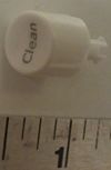
| 11 | Clean Push Button | 1 | 0.5 | activates 'clean' function on iron | plastic | injection molding | |
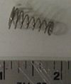
| 12 | Coil spring at base of pump | 2 | 0.5 | *** | Steel | *** | |
| 13 | Control Potentiometer | 1 | 35 | adjusts current cut-off to control temperature | *** | *** | |
| 14 | Crimp connector | 3 | 0.5 | connects leads from e-board to hot plate | plastic | injection molding | |
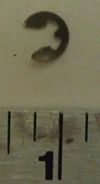
| 15 | E clip | 1 | 0.5 | *** | Steel | die pressed | |
| 16 | Electronics Assembly and Leads | 1 | 22 | controls auto-turn off feature of iron | PCB & components | *** | |
| 17 | Handle top cover | 1 | 26 | *** | plastic | injection molding | |
| 18 | Heater wire insulator assy | 1 | *** | *** | *** | *** | |
| 19 | Heater wire lead | 1 | 3 | connect control pot to hot plate | copper & insulation | *** | |
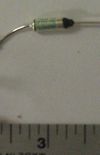
| 20 | Heating diode | 1 | 2 | controls current flow into heater | *** | *** | |
| 21 | Hot plate | 1 | 464 | heated part of iron | Steel | cast | |
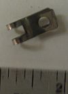
| 22 | HWIA insulator clip | 1 | 1 | attached insulation to hot plate | Steel | die pressed | |
| 23 | HWIA insulator tube | 1 | 3 | insulates heating wire from hot plate | plastic | *** | |
| 24 | Metal aesthetic cover | 1 | 74 | gives iron aesthetic appead | Steel | *** | |
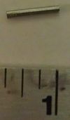
| 25 | Metal rod for steam selector rocker | 1 | 1 | holds steam selector cam in position and allows for rotation | *** | *** | |
| 26 | Mister and Steam buttons | 2 | 3.5 | user input to either mist or steam cloth | plastic | injection molding | |
| 27 | Mister assy | 1 | *** | pump, springs, tube, mister | *** | *** | |
| 28 | Mister hose | 1 | 0.5 | allows for water to flow from pump to mister | rubber | *** | |
| 29 | Mounting bracket bottom | 1 | 2 | holds selector cam mount to rest of iron assy | plastic | injection molding | |
| 30 | Pinion Gear to Attach to Potentiometer | 1 | 1 | pinion to adjust temperature of iron | plastic | injection molding | |
| 31 | Pinion pot adapter | 1 | 1 | converts pinion output to potentiometer input | plastic | injection molding | |
| 32 | Plastic sleeve around electronics | 1 | 0.5 | insulates electronics pcb | plastic | *** | |
| 33 | Power Cord Bend/Kink Protector | 1 | 4 | prevents power cord from kinking & allows for rotation | rubber | *** | |
| 34 | Power Cord | 1 | 128 | self-explanatory | copper & insulation, plastic, steel | *** | |
| 35 | Pump cylinder | 2 | 0.5 | functional part of mister/steamer, user depresses pump moving water from reservoir to appropriate output | plastic | injection molding | |
| 36 | Rack and Pinion Positioning Spring-Loaded Pin | 1 | 0.5 | allowd for set positioning of temperature select rack | Steel | *** | |
| 37 | Rack | 1 | 1.5 | transfers selector position to pinion | plastic | injection molding | |
| 38 | Rear screw | 1 | 0.5 | *** | Steel | *** | |
| 39 | Red Reset button | 1 | 0.5 | user input to reset the auto-off timer | plastic | injection molding | |
| 40 | Selector Handle Linear Slide | 1 | 2 | user-input to position temperature control setting | plastic | injection molding | |
| 41 | Selector Labelled With Notches for Fixed Positions Settings on Rack | 1 | 1.5 | temperature select settings visible to user, attached to rack with positioning grooves on bottom | plastic | injection molding | |
| 42 | Spring inside pump | 2 | 0.5 | resets pump to state of expansion to fill pump reservoir with more water | Steel | *** | |
| 43 | Steam Selector Cam With 4 Positioning Grooves | 1 | 1 | allows user to select how much steam to release on iron | plastic | injection molding | |
| 44 | Steam Selector Piston Gauge | 1 | 3 | adjusts opening at base of steam reservoir to change amount of steam outputted | brass | *** | |
| 45 | Steam Selector Tensioning Spring | 1 | 0.5 | keeps pressure on selector piston to prevent improper settings | Steel | *** | |
| 46 | Steam selector tube springs | 2 | 0.5 | prevents kinks/bends in tubes to mister/steamer | Steel | *** | |
| 47 | Steam tube | 1 | 2 | connects steamer pump to steam reservoir & output in bottom of iron | Steel | *** | |
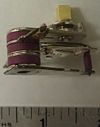
| 48 | Thermocouple plate | 1 | 0.5 | temperature sensitive material and geometry to 'activate' at selected temperature setting | *** | *** | |
| 49 | Water reservoir clear top cover | 1 | 54 | displays to user how much water they have put into the iron | plastic | injection molding | |
| 50 | Water reservoir outer hatch | 1 | 2 | opens to allow user to put water into reservoir of iron | plastic | injection molding | |
| 51 | Water reservoir seal assy | 1 | 1.5 | *** | *** | *** | |
| 52 | WRS base | 1 | 0.5 | *** | plastic | injection molding | |
| 53 | WRS seal | 1 | 0.5 | *** | rubber | *** | |
| 54 | WRS spring | 1 | 0.5 | *** | Steel | *** | |
| 55 | aluminum brace | 1 | 0.5 | *** | aluminum | die pressed & formed | |
| 56 | Rubber orange dirt seal | 1 | 4 | *** | rubber | *** | |
| 57 | Plastic bottom seal | 1 | 2 | *** | plastic | injection molding | |
| 58 | White plastic bottom cover | 1 | 55 | bottom half of reservoir, attachment points for pistons to draw water into them | plastic | injection molding | |
| 59 | Brass wire support | 1 | 0.5 | *** | brass | *** | |
| 60 | White silicone linear seal | 1 | 0.5 | Holds base support (#8) in place to metal base (#31) | Steel | *** | |
| 61 | White clip | 1 | 0.5 | Holds base support (#8) in place to metal base (#31) | Steel | *** | |
| 62 | Small silicone seal | 1 | 1 | *** | silicone | *** | |
| 63 | Screw 2 | *** | 0.5 | *** | Steel | *** | |
| 64 | Screw 3 | *** | 0.5 | *** | Steel | *** | |
| 65 | Screw 4 | *** | 0.5 | *** | Steel | *** | |
| 66 | Screw 5 | *** | 0.5 | *** | Steel | *** | |
| 67 | Screw 6 | *** | 0.5 | *** | Steel | *** |
Design for Manufacture and Assembly (DFMA)
Lorem ipsum dolor sit amet, consectetur adipiscing elit. Ut elementum elit vel tortor scelerisque auctor. Donec urna dui, eleifend eget adipiscing vulputate, feugiat id nisl. Donec mattis, quam in tincidunt ullamcorper, orci tellus condimentum dui, aliquet faucibus risus nunc et nunc. Vestibulum metus justo, volutpat sed consequat eget, mollis sed neque. Maecenas dignissim hendrerit malesuada. Aliquam dictum gravida orci ut rutrum. Fusce eros lectus, accumsan sed rhoncus eu, tempor sed magna. In ac lacus urna, ut cursus nisl. Curabitur ac dui nisl, in imperdiet orci. Aliquam quam dui, tincidunt quis volutpat quis, convallis a ipsum. Suspendisse quis molestie lorem. Nunc vel magna commodo nunc viverra tempor id blandit neque. Donec nec elementum ligula. Cras accumsan, urna eget dictum varius, arcu nunc porttitor tortor, sit amet feugiat nisl elit vitae elit. Proin eget tellus lectus, tempus tincidunt augue. Sed sagittis iaculis orci, sit amet tempus dui tincidunt in.
Manufacturing
Lorem ipsum dolor sit amet, consectetur adipiscing elit. Ut elementum elit vel tortor scelerisque auctor. Donec urna dui, eleifend eget adipiscing vulputate, feugiat id nisl. Donec mattis, quam in tincidunt ullamcorper, orci tellus condimentum dui, aliquet faucibus risus nunc et nunc. Vestibulum metus justo, volutpat sed consequat eget, mollis sed neque. Maecenas dignissim hendrerit malesuada. Aliquam dictum gravida orci ut rutrum. Fusce eros lectus, accumsan sed rhoncus eu, tempor sed magna. In ac lacus urna, ut cursus nisl. Curabitur ac dui nisl, in imperdiet orci. Aliquam quam dui, tincidunt quis volutpat quis, convallis a ipsum. Suspendisse quis molestie lorem. Nunc vel magna commodo nunc viverra tempor id blandit neque. Donec nec elementum ligula. Cras accumsan, urna eget dictum varius, arcu nunc porttitor tortor, sit amet feugiat nisl elit vitae elit. Proin eget tellus lectus, tempus tincidunt augue. Sed sagittis iaculis orci, sit amet tempus dui tincidunt in.
| Design for Manufacturing Features and Improvements | ||
|---|---|---|
| Design Objective | Strengths | Areas of Improvement |
| Minimize Part Count |
|
|
| Standardize Design Features |
|
|
| Keep Designs Simple |
|
|
| Multifunctional Parts |
|
|
| Ease of fabrication |
|
|
| Avoid Tight Tolerances |
|
|
| Minimize Secondary & Finishing Operations |
|
|
Assembly
Lorem ipsum dolor sit amet, consectetur adipiscing elit. Ut elementum elit vel tortor scelerisque auctor. Donec urna dui, eleifend eget adipiscing vulputate, feugiat id nisl. Donec mattis, quam in tincidunt ullamcorper, orci tellus condimentum dui, aliquet faucibus risus nunc et nunc. Vestibulum metus justo, volutpat sed consequat eget, mollis sed neque. Maecenas dignissim hendrerit malesuada. Aliquam dictum gravida orci ut rutrum. Fusce eros lectus, accumsan sed rhoncus eu, tempor sed magna. In ac lacus urna, ut cursus nisl. Curabitur ac dui nisl, in imperdiet orci. Aliquam quam dui, tincidunt quis volutpat quis, convallis a ipsum. Suspendisse quis molestie lorem. Nunc vel magna commodo nunc viverra tempor id blandit neque. Donec nec elementum ligula. Cras accumsan, urna eget dictum varius, arcu nunc porttitor tortor, sit amet feugiat nisl elit vitae elit. Proin eget tellus lectus, tempus tincidunt augue. Sed sagittis iaculis orci, sit amet tempus dui tincidunt in.
| Design for Assembly Features and Improvements | ||
|---|---|---|
| Design Objective | Strengths | Areas of Improvement |
| Minimize Part Count |
|
|
| Minimize Assembly Surfaces |
|
|
| Use Sub-assemblies |
|
|
| Mistake-Proof |
|
|
| Minimize Fasteners |
|
|
| Minimize Handling |
|
|
| Minimize Assembly Direction |
|
|
| Provide Unobstructed Access |
|
|
| Maximize Assembly Compliance |
|
|
Failure Modes & Effects Analysis (FMEA)
Lorem ipsum dolor sit amet, consectetur adipiscing elit. Ut elementum elit vel tortor scelerisque auctor. Donec urna dui, eleifend eget adipiscing vulputate, feugiat id nisl. Donec mattis, quam in tincidunt ullamcorper, orci tellus condimentum dui, aliquet faucibus risus nunc et nunc. Vestibulum metus justo, volutpat sed consequat eget, mollis sed neque. Maecenas dignissim hendrerit malesuada. Aliquam dictum gravida orci ut rutrum. Fusce eros lectus, accumsan sed rhoncus eu, tempor sed magna. In ac lacus urna, ut cursus nisl. Curabitur ac dui nisl, in imperdiet orci. Aliquam quam dui, tincidunt quis volutpat quis, convallis a ipsum. Suspendisse quis molestie lorem. Nunc vel magna commodo nunc viverra tempor id blandit neque. Donec nec elementum ligula. Cras accumsan, urna eget dictum varius, arcu nunc porttitor tortor, sit amet feugiat nisl elit vitae elit. Proin eget tellus lectus, tempus tincidunt augue. Sed sagittis iaculis orci, sit amet tempus dui tincidunt in.
| Failure Modes and Effects Analysis - Floor Bike Pump | |||||||||
|---|---|---|---|---|---|---|---|---|---|
| Item & Function | Failure Mode | Effects of Failure | S | Causes of Failure | O | Design Controls | D | RPN | Recommended Actions |
| Valve Nozzle Connector | Air leaking out of wheel | Bike tube loses air | 3 | Misalignment to valve | 2 | Check if it locks | 2 | 12 | Something to help user better secure nozzle properly |
| Does not lock | No air transfer into wheel | 3 | User not using it correctly | 2 | Check if it locks | 3 | 18 | Something that does not use a lock, Make it easier to lock | |
| Valve may not fit | No air transfer into wheel | 1 | Wrong valve type | 4 | Check if it locks | 4 | 16 | Make a universal valve, Provide adapters | |
| Pressure Gauge | Air leaking out of wheel | Won't display pressure | 2 | Broken gauge | 1 | Test in manufacturing plant | 2 | 4 | Better pressure gauge tube seal, Different pressure reading technique |
| Incorrectly calibrated | Displays incorrect pressure reading | 2 | Dropping gauge, Manufacturing error | 1 | Test in manufacturing plant | 7 | 14 | -- | |
| Handle rod | Bends | Can not apply downward force, Breaks rod | 5 | Bars are physically bent forward and not down, Damaged, Improper use | 2 | -- | 7 | 70 | Stronger rod |
| Tube | Air leaking out of wheel | Loss of air from tire | 3 | Misuse, Damage | 3 | -- | 4 | 36 | Tube wrapped in durable material |
Design for Environment (DFE)
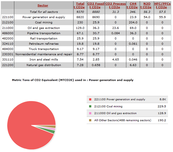
In analyzing our product, we were asked to consider its design and the impact design choices made on the environment. We used the Environmental Input-Output Life Cycle Analysis tool to analyze the production process of an iron and the use cycle of the products that are used in the operation of an iron (mainly water and electricity). The table below gives a rough estimate of the CO2 equivalent produced by the production and use cycle processes and the tax that would be implemented for each process. The end of the product’s life was not considered in the EIO-LCA analysis.
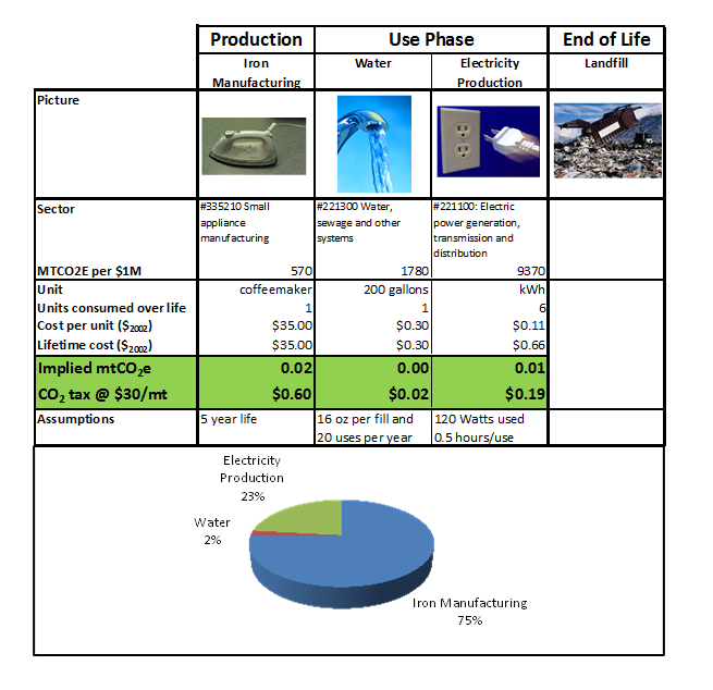
By observing the table and subsequent graph, the process that seems to be have the greatest CO2 impact and largest tax is the actual iron manufacturing, or the production phase. This result makes sense as the iron manufacturing process utilizes other sectors of the economy that have high environmental impacts.
Production
Iron production produces the greatest cost to the environment and therefore has the largest tax of any phase of the product’s life cycle. Iron manufacturing employs many other sectors of the economy. For our EIO-LCA analysis, we looked at the environmental impact of only $1 million economic production. The figures below provide a rough idea of what sectors are most involved in the small electrical appliance manufacturing, of which household appliance manufacturing composes only 5.14% (http://bea.gov/industry/io_benchmark.htm#2002data). When observing the following figures, it is important to remember household appliance manufacturing is a relatively small percentage of the entire sector represented.
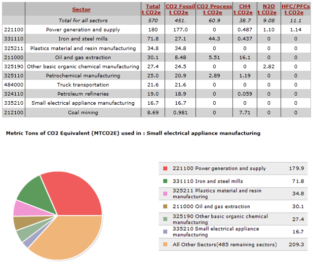
As depicted, the power production and supply as well as the iron and steel mills sectors both contribute to the largest percentage of CO2 equivalent released to the environment. Assuming that iron manufacturing composes all of the household appliance manufacturing sector, irons themselves would have an almost negligible environmental impact. However, the overarching sector does have a significant effect on the environment. We also ran the EIO-LCA model for the purchaser model and economic inputs to gather a realistic picture of the effect iron production would have on the environment. The figures shown below depict an annual economic model using the following assumptions:
U.S. Census Bureau – 115 Million U.S. households
Assumptions:
• Average life of iron is 5 years
• Each iron costs $35
• Each household in U.S. owns one iron
With these assumptions, we found the economic input of the model to be $800 million. The environmental impact of this model is shown below.
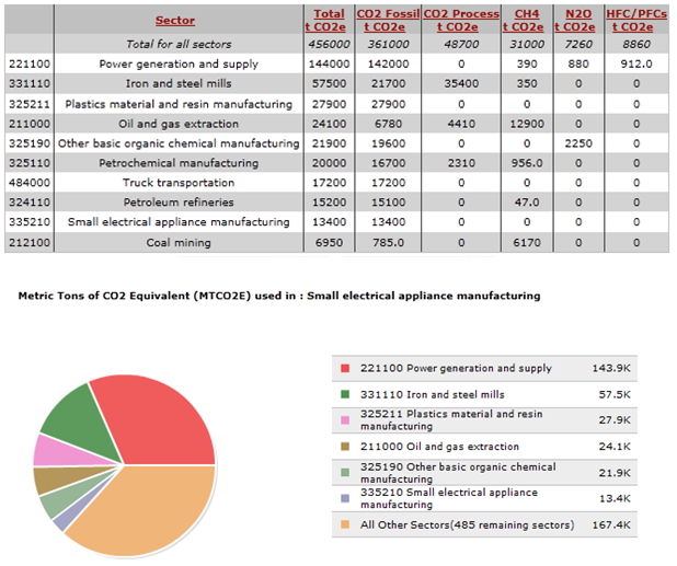
The pie chart depicting the sectors with the greatest environmental impact remains the same with power supply and generation as well as iron and steel mills dominating the percentage of CO2 equivalent in iron production. However, the overall CO2 equivalent is much greater. While an analysis of the entire iron sector was not required, our team believed an overall look at iron production in the U.S. could provide a scale to observe what a small change in the DFE of an iron would do on a large, entire sector scale.
Use
The use phase of an iron only consists of two main parts: power and water. However, each of these are minimized by what we assumed to be actual iron usage per year. These assumptions are stated in the overarching DFE table. Using the EIO-LCA tool, purchaser model, and an economic input of $1 million, the environmental impact of both power and water consumption were estimated. The following graphs show the EIO-LCA tool's output for both sectors.
Water Consumption
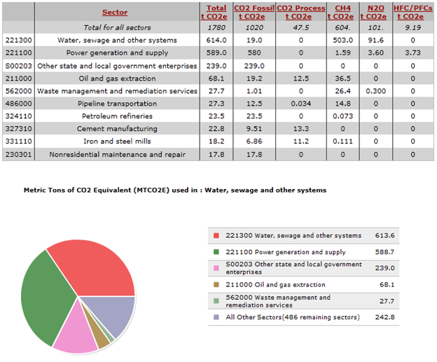
Economic Activity: $1 Million Dollars
Displaying: Greenhouse Gases
Number of Sectors: Top 10
Group Dynamic
Team Leader: Brian Koskey
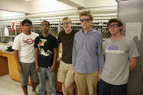
DFMA Lead: John Howland
FMEA Lead: John Ellis
DFE Lead: Alex Campbell
Wiki Page Programmer/Report Compilation: Pace Nalbone
References
Lorem ipsum dolor sit amet, consectetur adipiscing elit. Ut elementum elit vel tortor scelerisque auctor. Donec urna dui, eleifend eget adipiscing vulputate, feugiat id nisl. Donec mattis, quam in tincidunt ullamcorper, orci tellus condimentum dui, aliquet faucibus risus nunc et nunc. Vestibulum metus justo, volutpat sed consequat eget, mollis sed neque. Maecenas dignissim hendrerit malesuada. Aliquam dictum gravida orci ut rutrum. Fusce eros lectus, accumsan sed rhoncus eu, tempor sed magna. In ac lacus urna, ut cursus nisl. Curabitur ac dui nisl, in imperdiet orci. Aliquam quam dui, tincidunt quis volutpat quis, convallis a ipsum. Suspendisse quis molestie lorem. Nunc vel magna commodo nunc viverra tempor id blandit neque. Donec nec elementum ligula. Cras accumsan, urna eget dictum varius, arcu nunc porttitor tortor, sit amet feugiat nisl elit vitae elit. Proin eget tellus lectus, tempus tincidunt augue. Sed sagittis iaculis orci, sit amet tempus dui tincidunt in.
