Scooter
From DDL Wiki
Group Information
24-441 Spring 2012, Group 10
Claire Castleman: DFMA Lead
Elisha Clayton: DFE Lead
Michael Serebrennikov: Team Leader
Mathew Swisher: FMEA Lead
Vedant Saraf: Data Analysis
Product: Razor Scooter
Executive Summary
A kick scooter is a simple human-powered vehicle, composed of a small platform to stand on and handle bars to hold onto and steer, used as a means of transportation over short distances. As a case study, our team analyzed the Razor brand scooter, one of the most popular in the United States. The scooter was disassembled in order to gain an understanding of how it is manufactured and put together. Competitor products will also be examined in order to understand various solutions the manufacturers have come up with to common problems. An initial user study was conducted to determine shortcomings in the overall design. Following the data acquisition sessions, problems with both usage and design were found. One major problem proved that the scooter is difficult for larger users. Some of the construction also was found to be overly complicated. The goal of the overall project is to come up with an innovation to make the scooter easier or safer to use, to make the construction simpler, or to change its purpose by adding a utility attachment.
Major Stakeholders
Manufacturing
Manufacturers will care mainly about material and process costs. Some of their requirements are:
- Simple parts that can be mass produced
- A small number of unique parts
- Assembly with minimal effort
- Fast assembly time
- Low environmental effect of materials used
- Product/Material re-usability
Shipping
The shipping companies will be most concerned with spending the least amount of resources while transporting the maximum amount of product. Some of their requirements are:
- Maximum compressibility
- Low weight
- Low volume
- Reduce empty/wasted space
- Durable enough to withstand damage with minimal padding
Retailers
The primary goal of the retailer is to sell the product as quickly and for as high of a profit as possible. The retailers' requirements are:
- Appealing colors to customers
- Cheap product cost for maximal profit
- Minimal store floor-space usage
- Efficient packaging for minimal storage space
Potential Consumers and their concerns
Parents
- Low cost
- Reliable
- Safe
- Durable
- Something their kids will want and think is cool
Kids
- Fun
- Cool
- Light weight
- Trick friendly
College Students
- Portable
- Collapsible
- Light weight
- Easy to carry/store
- Energy efficient
- Cheap
- Durable
Product Details and Observations
Product Specifications
These product specifications are provided by the RazorUSA Company.[1] The particular model analyzed is the A2. This is the same as the model A, with the only difference being the addition of a wheelie bar and shocks.
- Material: Aluminum, Steel
- Number of Wheels: 2
- Front Wheel Material: Urethane
- Front Wheel Size: 98mm
- Rear Wheel Material: Urethane
- Rear Wheel Size: 98mm
- Wheel Base: 20.0 "
- Bearing Type: ABEC-5
- Maximum Weight Capacity: 143.0 Lb.
- Manufacturer's Suggested Age: 8 Years and Up
- Dimensions: 34.0 " H x 26.0 " L x 13.5 " W
- Weight: 6.0 Lb.
Product Observations
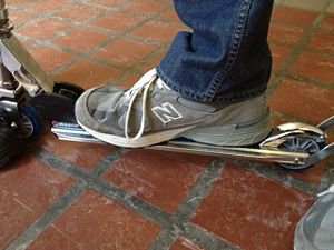
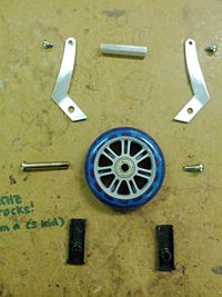
This particular model scooter has a rubber shock installed on the front wheel assembly (see image in the Bill of Materials Section below). The collapsing mechanism on the front of the scooter has locking grooves as a safety precaution when folding/unfolding the scooter. The operation of the folding mechanism is initiated with a very simple release lever that can be operated with one hand. This particular scooter comes with an optional wheelie bar. While arguments can be made that this is added to be able to do tricks and stunts, it mainly serves as a foot rest for the rider. It also adds a slightly "extreme" look to the scooter. In order to prevent the riders foot from sliding on the deck of the scooter, the Razor company added a sandpaper like sticker. While this has an important function, it also makes others aware that this scooter is in fact an authentic Razor, something that might appeal to younger children. The handlebars were coated in a comfortable cushy material in order to make riding more enjoyable for the user. The spoon brake system proved to be somewhat effective in slowing down the scooter, and is fairly easy to operate, making it stand out to parents who may be buying the scooters for their children and concerned for their safety.
Product Operation and Preliminary User Study
Product Operation
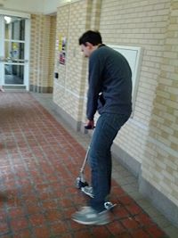
- The rider places hands on the handle bars and the inside foot on the deck for stability
- To propel the scooter, the rider pushes off with the outside foot and repeats this step until desired speed is reached
- The rider then lifts the outside foot off the ground and either lets it hover in the air or rests on the deck along with the inside foot until more speed is desired
- In order to stop, the rider either jumps, runs, or walks off the deck of the scooter or safely uses the inside foot to press down on the hinged fender that begins to stop the back wheel from any further rotational motion
How the Product Works Mechanically
- Propelled by a rider pushing one foot off the ground which makes the unidirectional wheels move in a rotational motion
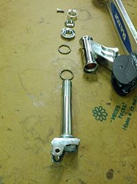
- To collapse the product, the handlebars are released by pressing two buttons that secure them in place atop the head-tube. The head-tube telescopes into itself and then folds down onto the deck by pushing a lever, which releases the tube from its locked position for easier storage and portability of the scooter.
- To stop the scooter, the rider presses a hinged fender brake down on the back wheel, creating a buildup of friction such that the scooter begins to slow down and gradually come to a stop.
Preliminary User Study
- The scooter is difficult for larger users. While there are bigger models, an adjustable universal model would be an optimal solution.
- The deck is too small for larger shoes to fit on fully
- Even at the maximum setting, the handle bars are too low for tall users
- Larger users can easily miss the brake while trying to stop
- A 143lb weight capacity limits the customer base severely
- Brake proves to be ineffective for stopping very quickly
- Sudden heavy braking can lead to locking the rear wheel, which in turn will wear it down
- Leaning back slightly can cause the user to fly backwards off the scooter
- The turning system proved to be difficult to use
- The direct connection to the front wheels causes a safety hazard at speed if the user turns the handlebars sharply
- User must turn really wide, or stop to turn
Potential Innovations
Following the usage study and product dissection study, the following list of innovations and improvements was compiles based on the analysis
- Wheel innovations
- Smoother ride
- Omnidirectional capable wheels
- Collapsible wheels
- Greater energy output with less effort input
- Easier/simpler collapsible mechanism
- Reduced weight
- Reduced volume when collapsed/increased potability
- Adjustments for larger users
- Telescoping handlebars
- Adjustable deck dimensions
- Multinational use
- Ski attachment for snow use
- Anti-lock brake system
- Hand operated disk brake
- Foot operated disk brake
- Removal of hard-to-use release buttons on handlebars
- Added utility attachments
- Broom/mop attachment for novelty cleaning product
- Ease of use modifications
- Foot operated collapsing mechanism
- Kick-up collapsing mechanism
- Foot deck rotational lock for more comfortable carrying
- More environmentally friendly materials/production process
Bill of Materials
In order to make the BOM more comprehensible, it is split up into separate subassembly BOMs. Repeating components share the same part number across subassemblies.
Front Wheel Subassembly
Shock and Wheel Attachment Subassembly
Lower Tube Subassembly
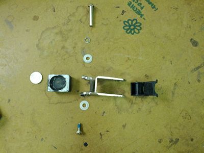
Collapsing Mechanism Subassembly
Front Deck Subassembly
Rear Wheel Subassembly
Top Tube Subassembly
Handle Bar Subassembly
Top Tube Adjustment Subassembly
Frame and Brake Subassembly
Design for Manufacturing and Assembly Analysis
Key Findings: There was a lot of room for improvement in the manufacturability and assemblability of the competitor's product. The main areas of improvement are minimization of unnecessary parts, standardization of components, creation of multifunctional parts, decreasing of secondary & finishing operations, and ease of handling of parts for assembly. Our competitor's product did excel in simplifying designs as well as choosing easily manufacturable parts and having subassemblies that can be tested separately. For detail on these findings, see the sections below.
Design for Manufacturing
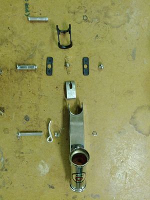
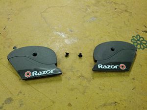
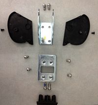
When analyzing our competitor's product, the Razor scooter A2, we found a lot of room for improvement of its manufacturability. In order to minimize the part count, it would be possible to design a collapsing mechanism that uses fewer parts than the current design, which has 18 parts. The plastic covers especially are mostly for decoration, with a secondary purpose of preventing young children from sticking their fingers into the locking mechanism. Even so, they are not essential to the design of the collapsing subassembly, and so only add unnecessary steps to the manufacturing and assembly processes. Throughout the whole product, plastic parts were added instead of using metal finishing processes. While this was resulted in fewer finishing steps, it added steps both in manufacturing and assembly.
The Razor scooter we disassembled also showed opportunities to standardize components, commonize the product line, and standardize design features. A lot of the screws used as fasteners were the same size, but several differed by one size, and a few even switched from Imperial to Metric sizing. By unifying the size and length of screws used, the scooter could take better advantage of economies of scale and utilize fewer tools in the manufacturing process.
Another area for possible improvement with respect to design for manufacture is the creation of multifunctional parts. No parts of the scooter are currently multifunctional, but there is a definite opportunity for the creation of such parts in our redesign. For instance, designing a brake that doubled as a lock for the handlebars when the scooter is in its collapsed position could remove the hassle of the handlebars swinging about loosely when unlocked.
A final place where manufacturability of the scooter could be improved is in its secondary & finishing operations. Every single aluminum piece that is visible on the outside of the scooter has been polished, and a sandpaper sticker was glued onto the deck when it would have been much easier and probably as effective to extend the extruded ribs across the deck of the scooter to add friction.
Despite all these areas for improvement, there were many ways the current design had kept manufacturability in mind, which we will remember as we consider our redesign. Some of the locking mechanisms on the scooter had minimized their part counts to about 2 parts (for example, the handlebar locking mechanisms each consisted of a button and a spring). Similarly, the scooter had some fairly sleek and simple designs, like the braking mechanism which, while not 100% functional, also only consisted of about 4 parts. In terms of ease of fabrication, most of the scooter was made of aluminum, which is easy to manufacture (when the aluminum is recycled) and very easy to machine. Most parts that were not aluminum were plastic, and the few remaining parts were made of steel or rubber. The plastic parts were all colored black by color dyes added to the injection molding process.
Overall, there are a few good designs we will keep in mind during our redesign, but even more opportunities for improvement which we hope to take advantage of in the next phases of our design process.
Design for Assembly
Our product was fairly complicated to disassemble, and in our limited experience attempting to reassemble some of its subassemblies, we discovered much room for improvement in its design. First of all, there were a lot of components for such a small, simple device. Some of these were flashy add-ons for marketing and design purposes, such as the shocks and wheelie bar, but others were useless or not essential to the function of the device, such as the numerous plastic pieces used as covers to hide unfinished parts. As well as removing unnecessary components, another way to minimize the part count is to remove fasteners, and utilize snap fitting or other means of attachment. A lot of screws were used in this device, and as we've discussed, they were already a hindrance for a number of other reasons.
Another area that could be improved upon is the ease of handling of parts for human assembly. There are a lot of ambiguous parts, such as screws and levers, which can be very difficult to tell apart and could easily be unified for easy assembly. Some of these parts are also symmetrical, but only work in one orientation. These parts should be made obviously unsymmetrical, so that it is obvious in which orientation they should be attached to the product. The orientation in which parts are attached is not uniform, either. Many parts have fasteners on multiple sides, and most of these are attached horizontally instead of the ideal attachment direction of straight down. A final cause for concern is that many of the parts of this scooter are assembled inside its small-diameter tubes, which are tight and do not facilitate easy movement or sight.
The main way in which the scooter utilized good design for assembly was its use of subassemblies that can be assembled and tested separately or outsourced. The wheel subassemblies are almost certainly tested and purchased separately, and most other subassemblies, such as the telescoping tubes, brake assembly, and handlebar assembly, can easily be tested without the entire product.
There are many ways to improve the ease of assembly in this product, many of which we will probably explore in the next phases of our project.
Failure Mode and Effect Analysis
In our analysis of the Razor scooter, we identified a number of different potential failure modes in using the competitor product. These failure modes can be found in the table below. This analysis was done using the FMEA method from section 14.5 of Dieter and Schmidt’s Engineering Design. By determining which failure modes have the highest RPN, we can determine which failure modes we need to pay extra attention to while redesigning or creating a new design.
| Item and Function | Failure Mode | Effects of Failure | S | Causes of Failure | O | Design Controls | D | RPN | Recommended Actions |
|---|---|---|---|---|---|---|---|---|---|
| Upper Head Tube (steering) | Pin that keeps tube telescoped fails, collar continues to have no purpose | Handle bars can detach from scooter, could cause crash | 7 | Stress in pin, low force in collar | 1 | Perform stress tests on the pin | 4 | 28 | Add a warning label on the scooter to keep collar tightened |
| Upper Head Tube (steering) | Button to lock tube in place sticks or breaks | Tube cannot reach full height | 4 | Spring fatigue or dirt/mud affecting button or spring | 2 | Perform fatigue tests on the spring | 3 | 24 | Include cleaning instructions in user manual |
| Collapsing Mechanism (folding for storage) | Spring, lever, or tensioner jams | Collapsing mechanism gets stuck in one position | 4 | Dirt/mud inside the assembly | 3 | Guides for the tensioner are designed to keep dirt out of the assembly | 3 | 36 | Include cleaning instructions in user manual or reduce the number of components that could get stuck |
| Collapsing Mechanism (folding for storage) | Spring breaks or comes loose | Collapsing mechanism no longer locks the scooter open or closed | 6 | Fatigue of the spring or guides failing to keep tensioner aligned | 1 | Perform fatigue testing on the spring | 2 | 12 | none |
| Axel (allows wheels to rotate) | Axel bends | Wheels will stop rolling smoothly or turning completely | 4 | Excessive load on the wheels caused by heavy rider or performing tricks | 5 | Test the effects of fatigue and stress on axles | 2 | 40 | Use a stronger material for axles and add a waring for maximum weight. |
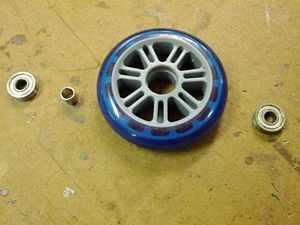
| Wheel Bearings (allows wheels to rotate) | Bearing breaks or jams | wheels stop rotating | 6 | Damage to bearings in a crash or dirt clogging the bearings | 2 | Check for damage to bearings and use sealed bearings | 1 | 12 | Make bearings easier to replace |
| Urethane Wheel Tread (traction for the wheel) | Rips, tears, and gouges in the tread | Prevents smooth riding of the scooter | 4 | Riding on rough terrain | 4 | Perform tests on the durability of the wheel treads | 2 | 32 | Use a stronger material for the wheel treads |
| Rear Wheel Tread (traction for the wheel & breaking) | Flat surfaces formed on the surface of the wheel. | Prevents smooth riding of the scooter | 3 | Breaking too hard and causing rear wheel to lock. | 7 | Test wear and durability of the rear wheel tread. | 3 | 63 | Use a stronger material for the rear wheel tread or redesign the breaking system |
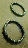
| Lower Tube Subassembly (steering) | Bearing gets jammed | Loose ability to steer scooter | 7 | Damage to bearing in a crash or dirt clogging the bearing | 2 | Check for damage to bearings | 1 | 14 | Improve the design to better seal the bearing |
| Collar from Lower Tube Subassembly (steering) | Collar too loose or threads get stripped | Steering becomes difficult or impossible, could result in crash | 7 | Loosening of screw, over tightening of screw, or damage to the collar | 3 | Check that collar is not loose | 1 | 21 | Include warning that all screws should be tight |
| Handle Bars (steering) | Elastic cable connecting handle bars breaks | Can lose handle bars | 2 | Excessive force on elastic cord or knot in cord comes loose | 5 | Test cord strength | 1 | 10 | Do not use a granny knots to connect handles |
| Handle Bars (steering) | Button connectors stop working | Handle bars won't stay attached | 5 | Spring fatigue or dirt/mud preventing making it difficult to use | 2 | Perform fatigue tests on springs | 3 | 30 | Make springs easy to clean |
| Handle Bar Padding (Makes grip on handle bars more comfortable) | Padding gets cut, scratched, or otherwise damaged | Grip becomes less comfortable | 1 | Not storing scooter properly, crashes, or normal use | 5 | none | 1 | 5 | none |
| Decorative Plastic End Covers (cover sharp edges) | Plastic covers could fracture or get knocked loose | Some sharp edges could be exposed and product would be less visually appealing | 1 | Fatigue or damage from normal use | 5 | Check that end covers are attached | 3 | 15 | Remove the end covers since they are mostly unnecessary |
The design of the competitor's product is generally very good from an FMEA standpoint. However, our FMEA showed that the failure of the three areas of most concern with the design of the scooter are the breaking system, the axles for the wheels, and the collapsing mechanism. Of these the breaking system is the largest problem, because it frequently creates flats on the wheels. This could be solved by redesigning the breaking system to prevent or reduce the likely hood of locking the wheels while breaking.
The second highest RPN is for the axles, which results from them being an important component of the design as well as being vulnerable to incorrect usage of the scooter. The possible improvements to the axles are limited to improving the materials to increase their strength or clearly labeling the maximum weight that the scooter is designed for.
The collapsing mechanism is an important component and had the third highest RPN value. Possible improvements to the mechanism are mostly limited to redesigning it to use fewer and more durable parts which should make it more reliable.
Design for Environment
It is extremely important to consider various environmental concerns and constraints of our product, the Razor Scooter. Reverse engineering for Green Product Design (REGPD) is an optimal technique in determining alternative “green” solutions to help reduce the overall environmental impact of our product in addition to a Life Cycle Assessment (LCA), whihc is simply a inventory and impact analysis of the product. A few other goals include but not limit to “reducing or eliminating the use of toxic materials, increasing energy efficiency, reducing the amount of material to perform the same function, extending the life of a product” (Comparini and Cagan, 1998).
Reverse Engineering involves dissembling a product into smaller assemblies and components in order to determine variability of materials, recyclability of materials, reusability, of parts, ease of disassembly, fastening methods, function relations, and areas of improvement (Comparini and Cagan, 1998), which was performed during the dissection activity. An “LCA is an environmental effect of raw materials taken from the environment (inputs) and the waste released back into the environment (outputs) by an industrial system” and contains fours stages: scoping, inventory, impact assessment, and improvement assessment (Comparini and Cagan, 1998).
For the Razor scooter, our definition of purpose is to get potential riders from one destination to the next using a one-foot propelling motion. The stages that the Razor Scooter go through are raw material acquisition, transport, production, distribution, use, and waste management. This specifically includes material selection, manufacturing process reduction, minimal parts and packaging, product efficiency, and reusability.
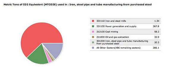
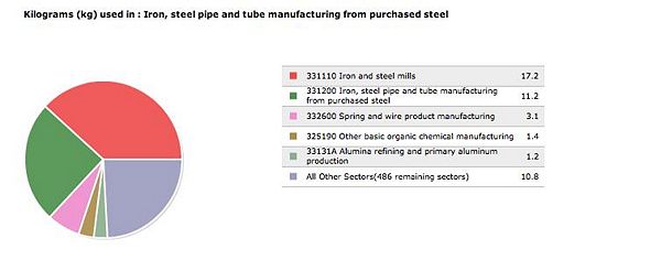
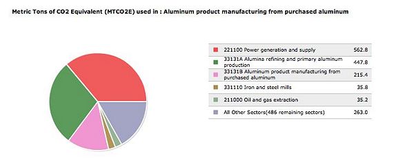
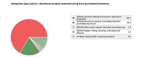
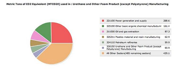
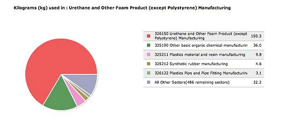
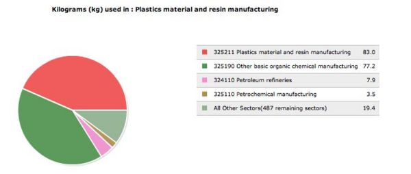
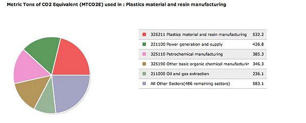
The Razor Scooter consists mostly of aluminum and steel for the body, urethane for the wheels, which are not necessarily the most environmental friendly, but the most durable when weighing various options. The graphs below illustrate different outputs based on each material in relevance to Greenhouse gases (GHG) and toxic releases. Each graph bases its emissions on $1M worth of economic activity.
Steel
Aluminum
Urethane
Other Plastics
References and External links
Comparini and Cagan, “Reverse Engineering for Green Design Products,” 1998
Brake device for a skate cart - Patent number 6139035 (stamped on brake of the scooter)
