Soda gun
From DDL Wiki
Contents |
Executive Summary
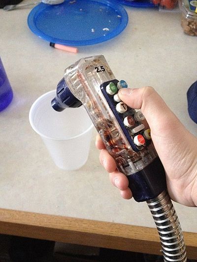
A soda gun is a handheld beverage dispensing device that is commonly used in bars, both personal and commercial, and restaurants. The gun allows the user to quickly dispense a variety of drink types from one common nozzle, optimizing the process of mixing beverages and providing high quality, fast, consistent service to customers. Soda guns operate by the opening and closing of valves in a plastic housing which allows the user to mix both flat and carbonated water along with a variety of syrups at different mixture ratios.
These soda guns can be purchased in a variety of forms with different numbers of drink options available (i.e. 4, 6, 8, 10, or 12 flavors). The gun consists of mainly plastic and standard purchase parts, driving production costs down. The use of standardized components means that the same screws, o-rings, tubing etc. can be used for each flavor line, regardless of how many are contained in the total gun assembly. This means that these sub-assemblies can be put together in the same factory, and then each gun variety can be assembled. Additionally, the parts are made of rubber, stainless steel, and plastic to avoid corrosion during operation and to prevent any failures from contact with fluids during operation and usage.
Macroscopically, the soda gun is attached to a variety of additional components, namely a water supply, a carbonator, syrup tanks, pumps, and in many cases, a chiller to provide cold beverages. For the purposes of this report, we will be examining the system from the syrup line through the nozzle of the gun. This report will include a variety of design analysis, including failure mode and effects analysis, design for engineering, design for manufacturing and assembly, and usability studies.
When examining fail modes, some key possibilities include leaking, losing the seal in the valves, or puncturing the hoses. Although these failures do not create a overly severe result, there is likely to be detectable inconvenience to the user, which will require some level of service from the soda gun manufacturer. Fortunately, the design of the gun allows for malfunctioning parts to be easily replaced with new standard purchased parts, allowing for fast, standardized, cheap service.
From an environmental perspective, the operation of the gun is likely to cause the largest impact, namely in the replacement of carbon dioxide (for the carbonation) and soda syrup. Within the gun itself, most custom parts are injection molded plastic, which translates to some losses in terms of scrap material, however, the lightweight and durable design makes the material selection a good choice for the gun's usage.
Overall, our initial impressions of the design of the soda gun are positive. There are many solid design decisions that were involved in the creation of the device. There are some examples of overuse of material that may be areas of improvement for the gun in terms of manufacturing cost, product weight, and environmental impact. Our team also hopes to assess the complete use of the gun in commercial establishments to determine if there are additional areas of grievance or needs for improvement in the design of the product. These areas may include ergonomics, leak-prevention, durability, and ease of use.
Use Study
1. What are the stakeholder needs?
- What attributes does the user need for from the product? What attributes does the retailer have?
- The User/Bartender:
- This product will be principally used by bartenders at commercial food and drink establishments. This product allows for multiple soda types to be served at a quick pace with uniform accuracy. The user expects that the product will complete the task at hand, namely separating different soda type.
- Some key qualities that the bartender expects are:
- Responsive, fast serving when each button is pressed
- Easy to understand button configuration and operating procedures allowing for operation with little training and muscle memory
- Consistent with any previously established industry standards for bartending and/or restaurant service
- Typically, these types of devices are built in an industry-standard layout.
- Any hoses or pumps must reach the full range of bar in case other employees need it
- It may be common for multiple bartenders and/or waiters to need access as well
- Easy to repair, easy to maintain, easy to clean
- Avoiding contamination issues will allow the establishment to be healthy and satisfy customer needs (no one wants a coke with orange soda residue in it)
- The user expects durable quality
- During peak hours, the gun may be thrown around, dropped etc.
- The user would like the product to be “Ergonometricly” friendly
- Over the course of a long shift, the user may hold and operate the gun for a long time
- Most products come with a holster that allows for storing and draining when the gun is not in use. The product must fit snugly in the holder to prevent any jostling, but also accessible enough to allow for easy removal and use, ideally with one hand.
- The Restaurant/Bar Owner:
- From the perspective of the owner, this product should be cheap to manufacture, require little maintenance, and be durable enough to last a long time after purchase. In many cases, the beverage company itself is responsible for the installation and maintenance of the gun, but if the owner can avoid these costs, he would be interested.
- From a purchasing standpoint, the bar owner would want the retail price of the soda gun to be as low as possible for the task at hand. It will be up to the bar owner to determine how many buttons the soda gun will need, though the guns typically come in 4,6,8,10, or 12 button varieties.
- In the case that a single establishment uses multiple guns, the owner would prefer that each unit performs similarly and can be serviced and purchased together.
- Bars tend to be small, cramped spaces, so the more compact the overall product is, the more successful it will be. Additionally, any components, including water lines, syrup containers etc. that can be stored below the bar and out of the way will prove favorable.
- The Retailer:
- The retailer of the gun wants the product to be aesthetically pleasing, which encourages customers to buy the gun and use it at their bar.
- He also expects the gun to be of high-quality to support his business, which may include water-resistance and consistent flow-rate. The gun should be as compact and light-weight as possible while performing the task at hand to allow for easier shipping, and giving bars the greatest amount of room to operate in, without bulky equipment in the way.
- The retailer wants to maximize the number of re-usable components in order to drive down manufacturing costs and allow for competitive pricing. For example, if all varieties of the soda gun can share some key commercial off-the-shelf components, then the overall production costs of the product line will be reduced. Additionally, the materials used in the gun should be minimal and commercially available, allowing for cheaper retail price and easy part substitution in case of malfunctioning components.
- Finally, the retailer wants the product to be easily explained and easily integrate-able into a bar. This allows for easier sales and a more diverse customer base.
2. How does the product work mechanically?
- - The user selects the desired soda type by pressing the corresponding button on the face of the handheld soda gun.
- - The downward motion of the button is translated across different butterfly clips that connect the appropriate combinations of valves (i.e. the carbonated water valve and the lemon-lime soda valve)
- - The downward motion of the pressed button and butterfly clip is translated through the gun using a pin and spring assembly, which opens a plastic valve connected to the corresponding soda type
- - Using a combination of a carbonator, pump and water tap, the gun mixes the soda at the desired flavor intensity through designated tubes in the gun.
- - A nozzle at the tip of the gun directs the flow in a concentrated area, and the user is able to fill a cup to the desired level.
- - To stop the flow of soda, the user releases the button, and the spring assembly moves the valve back into the closed position.
- Customization and Calibration:
- - The strength of the syrup in the mixture and what types of drinks are available are customizable and adjustable, allowing for the user to create a set up that best works for their demand and beverage company contracts.
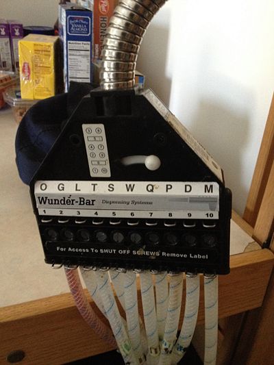
- - The gun contains a flow regulator housing along the tubes. This housing contains two valves for each type of soda: a shut-off valve and a flow adjustment valve
- - The shut off valve can be turned with a screw driver and causes the entire line for that particular soda to close. The valve can be released by turning the screw in the opposite direction
- - The flow adjustment valve has a similar mechanism as the shut-off valve, where a screw can be tightened or loosened using a screwdriver to obtain a desired mixture of syrup and water in the gun. This screw is used by the beverage company to ensure proper product flavor.
- - The handheld component of the gun also contains a secondary flow screw, which can be tightened or loosened using a screwdriver to control the flow rate of the water and allows to mix 2:1 or 1:1 drinks ([7]).
- Customization and Calibration:
3. How is the product used (step by step)?
- Set-Up
- Depending on the types of products that will be served (soda, juice, etc.) the handheld device should be modified to represent the correct drink types. These drink types will govern how the gun is installed and what types of performance the user should expect when using it (i.e. is the drink carbonated? what is the correct syrup ratio?)
- The gun should be attached to the desired dispensing system, which may include a water tap line, a carbonator, soda syrup tanks, and a syrup pump.
- Each soda type should be tested and adjusted to meet the required mixture ratios and flow rates. These properties can be adjusted by tightening or loosening the adjustment screws on the flow regulator assembly and on the back of the handheld device.
- To calibrate each drink type, adjust the flow regulator screws on the flow regulator housing assembly for each tube by using a screwdriver to tighten or loosen each screw.
- To calibrate the overall flow rate of the gun, adjust the flow rate screw on the back of the handheld gun using a screwdriver to tighten or loosen the screw.
- The bartender/user must learn which buttons go to each soda based on the position on the gun and the lettering on each button. Ideally, this step is an industry standard, allowing for any user to quickly pick up the device and operate it correctly
- End Use
- Remove gun from holster and place handheld component in users hand, with the buttons facing up
- Point the plastic nozzle downward, in the direction of the cup that is to be filled
- With the user's thumb, press the button corresponding to the desired drink type downward, toward the base of the gun
- While the button is held depressed, the gun will fill the cup to the desired level
- When the desired fill level has been reached, remove thumb from the button, allowing it to return to its original position
- Re-holster the soda gun and serve the recently poured drink to the customer
- Set-Up
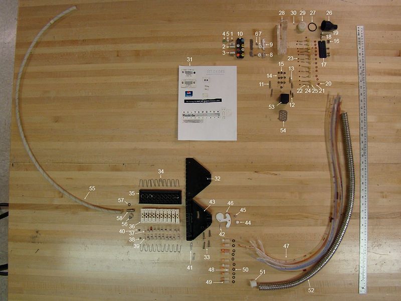
Assembly with Labeled Parts
Bill of Materials
| Part # | Part Name | QTY | Weight (g) | Function | Material | Manufacturing | Image |
|---|---|---|---|---|---|---|---|
| Soda Gun Sub-Assembly | |||||||
| 1 | "Round head 1/2" Length 1/8th" Dia Phillips" | 2 | <1 | Fastens button panel | Stainless Steel | Std Purchase Part | |
| 2 | Elliptical Soda Button (Top) | 2 | <1 | User input button for soda, designates type | Plastic | Injection Molded | |
| 3 | Eliptical Soda Button (Bot) | 2 | <1 | Translates input key face to release soda | Plastic | Injection Molded | |
| 4 | Circle Soda Button (Top) | 8 | <1 | User input button for soda, designates type | Plastic | Injection Molded | |
| 5 | Circle Soda Button (Bot) | 8 | <1 | Translates input key force to release soda | Plastic | Injection Molded | |
| 6 | "Flat head 1/4" len 1/8" dia philips" | 2 | <1 | Fastens panel to gun body | Stainless Steel | Std Purchase Part | |
| 7 | Plastic Washer (For Part #6) | 2 | <1 | Spacing | Plastic | Injection Molded | |
| 8 | Small Butterfly Clip | 2 | <1 | Presses down the valves for non-carbonated drinks | Stainless Steel | Die Cast, punched | |
| 9 | Large Butterfly Clip | 2 | <1 | Presses down the valves for carbonated drinks | Stainless Steel | Die Cast, punched | |
| 10 | Button Panel, blue, 10 button | 1 | 12 | Holds all buttons in place | Plastic | Injection Molded | |
| 11 | "Round head 1" len 1/8" dia flat screw" | 2 | <1 | Fastened gun to hose base | Stainless Steel | Std Purchase Part | |
| 12 | "Round head 1/2" len, 1/8" dia flat screw" | 2 | <1 | Fastened gun to hose base | Stainless Steel | Std Purchase Part | |
| 13 | "Hexagon, 7/8" len, 1/8" dia threaded head (Receives Part #11)" | 2 | <1 | Fastened gun to hose base | Stainless Steel | Std Purchase Part | |
| 14 | Nozzle caps, clear plastic | 10 | <1 | Reduces hose diameter into gun base | Plastic | Injection Molded | |
| 15 | O-ring, rubber | 10 | <1 | Seals hose to gun base | Rubber | Std Purchase Part | |
| 16 | "Round head, 1/4" len, 1/8" dia, philips screw" | 5 | <1 | Fasten back panel to gun | Stainless Steel | Std Purchase Part | |
| 17 | Back panel, blue | 1 | 6 | Provides grip to back of gun, aesthetic | Plastic | Injection Molded | |
| 18 | "Secondary flow adjustment screw, 1/2" len, 1/8" dia, flat head" | 1 | <1 | Allows to mix 2:1 and 1:1 beverages | Stainless Steel | Std Purchase Part | |
| 19 | Rubber o-ring for Part #18 | 1 | <1 | Seals screw, provides snug fit | Rubber | Std Purchase Part | |
| 20 | "O-ring, rubber, red 1/4" dia" | 12 | <1 | Seals valve assy | Rubber | Std Purchase Part | |
| 21 | Clear plastic spring cap | 12 | <1 | Caps spring (Part #22) | Plastic | Injection Molded | |
| 22 | "Small spring, 1/2" len" | 12 | <1 | Translates input to opening valve, reset valv when released | Stainless Steel | Std Purchase Part | |
| 23 | "O-ring, rubber, red, 1/8" dia" | 12 | <1 | Seals (Part #24) to valve assy | Rubber | Std Purchase Part | |
| 24 | Pin | 12 | <1 | Holds valve in place, allows for vertical motion | Stainless Steel | Std Purchase Part | |
| 25 | Plastic valve | 12 | <1 | Glued to pin, opens/closes each syrup line | Plastic | Injection Molded | |
| 26 | Soda gun Nozzle, plastic, blue | 1 | 13 | Focuses final soda dispense | Plastic | Injection Molded | |
| 27 | "Black, O-ring, rubber, 1" dia" | 1 | <1 | Seals nozzle head to gun | Rubber | Std Purchase Part | |
| 28 | Soda gun body | 1 | 113 | Directs and organizes flow for all fluids exiting soda gun | Plastic | Machined in five layers, irreversibly sealed together, post-drilled | |
| 29 | Soda gun nozzle base | 1 | 10 | Creates central location for syrup+soda to mix and exit gun | Plastic | Turned, glued to soda gun body | |
| 30 | Soda gun nozzle base retaining pins | 2 | <1 | Create fixture points for nozzle base | Stainless Steel | Turned | |
| 31 | Stickers (misc.) | 12 | <1 | Provides information and instructions about product, barcodes, safety information use, and beverage types | Paper | Printed | |
| Flow Regulator Sub-Assembly | |||||||
| 32 | Plastic Regulator Backing | 1 | 41 | Hold tubes to regulator | Plastic | Injection Molded | |
| 33 | "flat top, 3/4" len, 1/4" dia, philips head screw" | 4 | 3 (ea) | Fastens regulator casing together | Stainless Steel | Std Purchase Part | |
| 34 | Tube retainer, retaining clips | 20 | <1 | Retain the tube retainers to base | Stainless Steel | Std Purchase Part | |
| 35 | Tube housing, main body | 1 | 46 | Holds the tube housing | Plastic | Injection Molded | |
| 36 | Tube housing, single holder | 10 | 6 | Connects two sides of tubes | Plastic | Injection Molded | |
| 37 | Shut-off screw | 10 | <1 | Shuts off soda flow | Plastic | Injection Molded | |
| 38 | "Shut-off screw o-ring 1/4" dia, rubber" | 10 | <1 | Seals shut-off screws | Rubber | Std. Purchase Part | |
| 39 | Flow adjustment screw | 10 | <1 | Adjusts syrup/water ratio | Plastic | Injection Molded | |
| 40 | "Flow adjustment screw o-ring, 1/4" dia, rubber" | 10 | <1 | Seals adjustment screw | Rubber | Std. Purchase Part | |
| 41 | "Housing retaining pin 1", 5/32" dia" | 2 | 4 | Holds tube housing halves together | Stainless Steel | Cut to length | |
| 42 | Pivot pin for separating mechanism | 1 | <1 | Creates pivot point for half separator of plastic reg. housing | Stainless Steel | Cut to length | |
| 43 | Plastic regulator fronting | 1 | 63 | Hold tubes to regulator | Plastic | Injection Molded | |
| 44 | Cap of separating mechanism, white | 1 | <1 | User interaction point for separator mechanism | Plastic | Injection Molded | |
| 45 | Cap of separating mechanism pivot | 1 | <1 | Held cap to main separating body | Stainless Steel | Turned/Lathed | |
| 46 | Main separator body | 1 | 5 | Separates the halves | Plastic | Injection Molded | |
| Small Tube Sub-Assembly | |||||||
| 47 | Small Eaton Synflex Tubing (4203-0400) | 10 | 11 | Carries syrup to gun | Plastic | Std. Purchase Part | |
| 48 | Plastic Hose Clamping Ring (orange) | 10 | <1 | Connects syrup tubing to end cap | Plastic | Injection Molded | |
| 49 | Ridged fitting, plastic | 10 | <1 | Connects tubing to dispensing system | Plastic | Injection Molded | |
| 50 | "O-ring, rubber, 3/8" dia, black" | 10 | <1 | Seals fitting | Rubber | Std. Purchase Part | |
| 51 | Plastic, anti-friction ring | 1 | 1 | Prevents metal casing from cutting tubing | Plastic | Injection Molded | |
| 52 | Outer tubing casing, metal | 1 | 200 | Gathers all tubes, protects against wear, allows for flexible movement | Stainless Steel | Std. Purchase Part | |
| 53 | Soda gun base connector | 1 | 11 | Connects handheld gun to the tubing casing | Plastic | Injection Molded | |
| 54 | Tubing holding plate | 1 | 10 | Holds all tubes in correct positions for handheld gun | Stainless Steel | Cut, stamped | |
| Large Tube Sub-Assembly | |||||||
| 55 | Rev-Flex P-E Hose | 10 | 63 | Carries liquid from source to soda gun assembly | Plastic | Std. Purchase Part | |
| 56 | Hose clamp | 10 | 2 | Fastens metal fitting to hose | Stainless Steel | Std. Purchase Part | |
| 57 | O-ring, rubber, black | 10 | <1 | Seals fitting to assembly | Rubber | Std. Purchase Part | |
| 58 | Fitting, metal | 10 | 7 | Allows liquid to flow from one tubing to another | Stainless Steel | Machined | |
Design for Manufacturing and Assembly [DFMA]
To observe areas of simplification and improvement for the system, a manufacturing and assembly analysis was run to look at ways to optimize the system for simplicity, ease of manufacture, and component minimization. While part minimization is limited by the number of soda types that can flow through the gun and their respective repeating subassemblies, the designs were not fully optimal.
For manufacturing, we find that good design choices included the repeatable system with the multiple lines, standardized parts, multi-functional parts, good material selection (non-corrosive, durable, and easily formed), and the use of O-rings to create tight seals without pushing tolerances. The main areas of improvement we suggest are using snap-fit geometry to minimize part count, and finding an easier to way to manufacture the soda gun body which is made from acrylic (which is difficult to work with) and is incredibly complicated.
We found that major improvements could be made in the assembly process. The regulator could be eliminated and labeling could be generally simplified. Also, the assembly process could be streamlined by examining the flow regulator and removing the unnecessary components.
Manufacturing
| Guideline | Good Design Choices | Areas for Improvement |
|---|---|---|
| Minimize Part Count: Eliminate fasteners, part consolidation |
|
|
| Standardize Components: Take advantage of economies of scale and known component properties |
|
|
| Commonize Product Line: Economies of scale, minimum training and equipment |
|
|
| Standardize Design Features: Common dimensions for fewer tools and machine set-ups |
|
|
| Keep Designs Simple: Simplest way to achieve needed functionality |
|
|
| Multifunctional Parts: simplifies by letting one component serve many functions |
|
|
| Ease of fabrication: Choose materials easy to work with |
|
|
| Avoid tight tolerances: because they cause cost and machining time to increase drastically |
| None
|
| Minimize secondary or finishing operations: |
|
|
| Take advantage of special process properties: like coloring plastic |
|
|
Assembly
| Guideline | Good Design Choices | Areas for Improvement |
|---|---|---|
| Minimize Assembly Surfaces: and sequence them |
|
|
| Use subassemblies: can be tested and assembled separately, or outsourced |
|
|
| Mistake-proof: unambiguous, unique assembly orientation | None
|
|
| Minimize fasteners: snap fits and part consolidation | None
|
|
| Minimize handling: position for insertion or joining is easy to achieve |
|
|
| Minimize assembly direction: ideal is to add each component from top to base |
| None
|
| Provide unobstructed access consider assembly path | None
|
|
| Maximize assembly compliance:' chamfers and radii help assemble parts with variance |
| None
|
| Minimize extraneousness: features that have no functional use but aid with assembly | None
| None
|
Failure Mode and Effect Analysis [FMEA]
We performed a Failure Mode and Effect Analysis on the soda gun. We considered individual parts, sub assemblies, and user interaction when conducting this analysis. The primary focus of this analysis is to identify the cause and effect of potential failure modes in our system. We began by gathering a list of parts and sub assemblies and different failure modes for each part. We then discussed the effects of each failure, the causes of each failure, and any design controls implemented to the part (if any). We scored the severity of failure (S), probability the failure occurs (P), and ease of detection (D) on a scale from 1-10 to determine an ultimate risk priority number (RPN). Parts with higher RPN are of highest priority when considering a redesign for a safer system.
We found that the main problem that we are trying to prevent is leakage and that the most like place for this problem to occur is at tubing connections. Through our analysis, we suggest analyzing tolerances and factors of safety to prevent leakage.
To rate the severity of the failure, we used a 1-10 scaling system. Below is a table guideline of number rating and description.
| Rating | Severity Description |
|---|---|
| 1 | The effect is not noticed by the customer |
| 2 | Very slight effect noticed by customer, does not annoy or inconvenience customer |
| 3 | Slight effect that causes customers annoyance, but they do not seek service |
| 4 | Slight effect, customer may return product for service |
| 5 | Moderate effect, customer requires immediate service |
| 6 | Significant effect, causes customer dissatisfaction; may violate a regulation or design code |
| 7 | Major effect, system may not be operable; elicits customer complaint; may cause injury |
| 8 | Extreme effect, system is inoperable and a safety problem. May cause severe injury. |
| 9 | Critical effect, complete system shutdown; safety risk |
| 10 | Hazardous; failure occurs without warning; life-threatening |
Source: Dieter and Schmidt, Engineering Design
To rate the probability that failure occurs, we also used a 1-10 scaling system as described below.
| Rating | Approx. Probability of Failure | Description of Occurrence |
|---|---|---|
| 1 | < 1 x 10^(-4) | Extremely remote |
| 2 | 1 x 10^(-5) | Remote, very unlikely |
| 3 | 1 x 10^(-5) | Very slight chance of occurrence |
| 4 | 4 x 10^(-4) | Slight chance of occurrence |
| 5 | 2 x 10^(-3) | Occasional occurrence |
| 6 | 1 x 10^(-2) | Moderate occurrence |
| 7 | 4 x 10^(-2) | Frequent occurrence |
| 8 | 0.20 | High occurrence |
| 9 | 0.33 | Very high occurrence |
| 10 | > 0.50 | Extremely high occurrence |
Source: Dieter and Schmidt, Engineering Design
Finally, to rate the detection of failure, we used a similar table to guide us in number rating.
| Rating | Description of Detection |
|---|---|
| 1 | Almost certain to detect |
| 2 | Very high chance of detection |
| 3 | High chance of detection |
| 4 | Moderately high chance of detection |
| 5 | Medium chance of detection |
| 6 | Low chance of detection |
| 7 | Slight chance of detection |
| 8 | Remote chance of detection |
| 9 | Very remote chance of detection |
| 10 | No chance of detection; no inspection |
Source: Dieter and Schmidt, Engineering Design
Below is our completed FMEA table with descriptions and number rankings.
| Item and Function | Failure Mode | Effects of Failure | S | Causes of Failure | O | Design Controls | D | RPN | Recommended Actions |
|---|---|---|---|---|---|---|---|---|---|
| O-Ring: Seals tubing and valves | Break or Snap off | loss of fluid control | 4 | stress/ fatigue in material | 2 | Indention in tubing or valve where each o-ring is placed | 4 | 32 | Thicker o-ring |
| O-Ring: Seals tubing and valves | not sealing properly | fluid leakage | 4 | material overstretched | 1 | Indention in tubing or valve where each o-ring is placed | 5 | 20 | more flexible o-ring |
| Soda Button Valve: open/close to release/prevent fluid | not fully opening | loss of soda output | 4 | valve not properly aligned | 5 | spring and butterfly clips align valves | 3 | 60 | tighter tolerances to maintain alignment |
| Soda Button Valve: open/close to release/prevent fluid | not fully closing | endless soda output/ leakage | 4 | valve not properly aligned | 5 | spring and butterfly clips align valves | 3 | 60 | tighter tolerances to maintain alignment |
| Soda Tubing: pathway for fluid to flow from its original container into the soda gun | puncturing/ kinking | leaking | 4 | ends of tubing catch on metal connectors | 4 | metal casing gathers individual tubes | 2 | 32 | plastic buffers between metal connectors and tubing, rounded edges on connectors |
| Soda Tubing: pathway for fluid to flow from its original container into the soda gun | puncturing/ kinking | incorrect soda ratios | 2 | ends of tubing catch on metal connectors | 3 | metal casing gathers individual tubes | 3 | 18 | plastic buffers between metal connectors and tubing, rounded edges on connectors |
| Soda button spring: stores mechanical energy when valve is pressed, allowing valve to open and close easily | sticks and doesn't properly compress | valves and buttons would not work | 3 | fluid debris build up around spring | 1 | none | 6 | 9 | ensure spring is anti-corrosive |
| Tightening Screws: adjust syrup ratio allowed into soda gun system | over/ under tightened | incorrect syrup ratio | 2 | user misjudges amount of rotations needed to provide correct flow rate | 3 | none | 3 | 18 | provide some guidelines that help the user identify how many rotations signify the correct flow rate |
| Tightening Screws: adjust syrup ratio allowed into soda gun system | stripped screw head | loss of flow control | 4 | user applies too much pressure to screw head | 2 | none | 2 | 16 | consider re-selecting a stronger material less prone to stripping |
| Tube clamps: fasten tubes to soda gun | clamps fall off | loss of flow control | 2 | contact stress concentration on clamping | 2 | none | 4 | 16 | redesign clamps for higher factor of safety |
| Nozzle: consolidates flow and directs it into drinking cup | fatigue, cracking | soda leaks and sprays in unwanted direction | 3 | too high of fluid pressure | 2 | none | 1 | 6 | use a stronger plastic to better resist fatigue |
| Nozzle: consolidates flow and directs it into drinking cup | fatigue, cracking | soda leaks and sprays in unwanted direction | 3 | user misuses, drops soda gun onto nozzle | 3 | none | 1 | 9 | use a stronger plastic to better resist fatigue |
| Plastic Buttons: designate soda type and release valves | fatigue, overuse | loss of selection modes | 3 | contact stress from overuse or user misuse | 3 | none | 1 | 9 | design stronger connection for buttons to resist early fatigue |
| Soda gun: Directs and organizes flow for all fluids exiting soda gun | clogging from syrup build up | product (at least one soda line) becomes nonfunctional | 5 | not properly cleaned/maintained | 3 | none | 1 | 15 | implement cleaning feature to clear out all fluid lines |
| Soda gun: Directs and organizes flow for all fluids exiting soda gun | fatigue, cracking | product (at least one soda line) becomes nonfunctional | 5 | user misuse, dropping or slamming product | 3 | none | 1 | 15 | design soda gun with a higher factor of safety to resist early fatigue |
| Butterfly clips: align valves and provide normal force when button is pressed | jam or stick | valves don't work properly, potentially releasing multiple soda syrups | 2 | contact stress knocks clips out of place | 3 | pocket cut in soda gun body for clip placement | 5 | 30 | fasten butterfly clips down with screw or adhesive |
| Regulator housing: gathers, labels, and aligns soda syrup tubes | fatigue, cracking | tubes not consolidated | 1 | contact stress on part | 2 | none | 1 | 4 | redesign housing to resist early fatigue, consider stronger plastic |
| Regulator housing: gathers, labels, and aligns soda syrup tubes | syrup label sticker falls off | loss of syrup organization; can't tell which tube holds which syrup | 2 | liquid spills on label, causing adhesive to wear | 2 | none | 1 | 4 | eliminate sticker all together and implement better labeling system |
Design for Environment [DFE]
We found that the soda gun is optimized for multiple users to deliver a variety of soda drinks from the same location. In terms of functional optimizations, the soda gun could be made more ergonomic and more easily cleaned. These changes could improve the life of the gun and its ease of use. Individual parts can be optimized to take into account the degradable nature of the materials used, but the added cost of different materials could make environmentally friendly materials less practical to use or even more wasteful. Further, the packaging of the gun could be optimized to reduce waste and save on transportation costs. Seeing as the gun is usually bought in combination with other equipment, the total packaging and transportation costs would need to be examined for the purchased assembly as a whole. Finally, the parts can be made easily replaceable (especially the O-rings) which would prolong the life of the soda gun and cause less waste by allowing the gun to be reused instead of thrown away. This can be done by standardizing the part, making the gun easy to take apart with only simple tools, and providing consumers with easy-to-follow electronically-delivered repairing instructions.
EIOLCA - Economic input-output life cycle assessment
In this section, we are studying the environmental impact of a whole soda dispensing system, considering the emission of greenhouse gases in the form of equivalent metric of tons of CO2 (mtCO2e). We will use the model from eiolca.net . The US 2002 Producer database has been used and the prices entered accordingly. Note that the producer's costs for the whole system, 1 gal of syrup and 20lb of CO2 are only the result of our estimates, knowing that in 2013, the consumer price of a system like this would be around $1500, that 1 gal of syrup trades for around $15 and a 20lb CO2 tank refill costs about $20.
| Production | Use | ||||
|---|---|---|---|---|---|
| Item purchased | Soda Gun System | Tap Water | Syrups | Electricity | CO2 |
| (a) Picture | |||||
| (b) Economic Sector # and Name | 333319 : Other Commercial and Service Industry Machinery Manufacturing | 221300: Water, sewage and other systems | 311930 : Flavoring syrup and concentrate manufacturing | 221100 : Power generation and supply | 325120 : Industrial gas manufacturing |
| (c) Reference Unit | 1 system | 1 gal | 1 gal | 1 kWh | 1 20lb tank of CO2 |
| (d) Units Consumed per Product Life | 1 for 10 years | 68'437.5 | 13'687.5 | 1609.7 | 912.5 |
| (e) Cost per Unit ($ 2002) (Production) | $ 700 | $ 0.00154 | $ 3 | $ 0.11 | $ 5 |
| (f) Lifetime Cost = (d)*(e) ($ 2002) | $ 700 | $ 105.4 | $ 41062.5 | $ 177.07 | $ 4562.5 |
| (g) Economy-wide mtCO2e released per $1M of output for sector (b) | 533 | 1780 | 395 | 9370 | 5510 |
| (h) Implied mtCO2e released per Product Life = (g)*(f)/$1M | 0.373 | 0.188 | 16.220 | 1.659 | 25.139 |
| (i) CO2 Tax @ $30/mtCO2e = $30*(h) | $ 11.19 | $ 5.64 | $ 486.6 | $ 49.77 | $ 754.17 |
| (j) Assumptions | Lifetime : 10 years | 360 cups of soda per day -> 300 cups of water = 18.75 gal per day | 1:5 mix with water -> 60 cups of syrup = 3.75 gal per day | gun is used for 5 seconds per drink / carbonator using 0.432 kW / water pump using 0.36 kW / chiller using 0.09 kW / => 0.44 kWh per day | 15 gal of syrup per tank |
Carnegie Mellon University Green Design Institute. (2014) Economic Input-Output Life Cycle Assessment (EIO-LCA) US 2002 (428 sectors) Purchaser model [Internet], Available from: <http://www.eiolca.net/> [Accessed 2 Feb, 2014]
Comments
1) GHG emissions
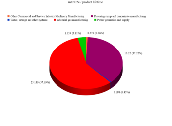
We see that the production of the soda gun system itself only produces a minimal amount of the greenhouse gas emissions. Most of the GHG emissions actually come from the resources needed to operate it : carbon dioxide is responsible for a big part, and surprisingly, the production of syrup too. The following table summarizes that :
| Sector | mtCO2e / product lifetime | % of total mtCO2e |
|---|---|---|
| 333319 : Other Commercial and Service Industry Machinery Manufacturing | 0.373 | 0.85% |
| 221300: Water, sewage and other systems | 0.188 | 0.43% |
| 311930 : Flavoring syrup and concentrate manufacturing | 16.22 | 37.22% |
| 221100 : Power generation and supply | 1.659 | 3.81% |
| 325120 : Industrial gas manufacturing | 25.139 | 57.69% |
Unfortunately, the quantity of syrup is determined by our tastes and cannot be changed by a redesign of our product. Concerning the CO2, as it is not only used to carbonate the water but also to drive the syrup pumps, we can imagine that the quantity of CO2 needed could be reduced if the efficiency of the syrup pumps were increased. From these sources ( [1], [2] ), one 20lb CO2 tank is needed for 15 gal of syrup (= 90 gal of soda). But other sources ( [3], [4], [5] ) state that a 20lb tank alone could carbonate more than 1000L of water (= 264 gal) ! As electricity has globally a smaller impact, the following question should be reconsidered : Why aren't the syrup pumps running with electricity?
2) Impact of a $30 CO2 tax per mtCO2e
As we can see in the table above, the use of a considerable amount of syrup and CO2 creates a large amount of equivalent CO2 emission and this is directly translated into an incredible tax. Let's recapitulate this :
| Soda Gun System | Tap Water | Syrups | Electricity | CO2 | |
|---|---|---|---|---|---|
| Lifetime cost ($2002): | 700 | 105.4 | 41'062.5 | 177.07 | 4562.5 |
| CO2 tax ($): | 11.19 | 5.64 | 486.6 | 49.77 | 754.17 |
| % of lifetime cost : | 1.59% | 5.35% | 1.19% | 28.11% | 16.53% |
Now, things look differently : for the syrups, the tax seemed to be big, but compared to the production cost of it, it gets to the same order than for the system and the water : a few percent. The CO2 tax is big in absolute value and reveals itself to be important as a relative value as well : 16.5%. What really comes out of this table is the relative tax on the electricity : 28% ! Maybe the choice to run the syrup pumps on CO2 instead of electricity is not as bad as thought before, from this point of view.
All in all, a redesign of the product should minimize the amount of CO2 and electricity needed to stay competitive.
3) Comments on the accuracy
- Concerns on the choice of the different models (economic sectors) :
For the resources needed to use our product (water, syrup, power), appropriate economic sectors were fortunately available and are therefore accurate.
The category for the CO2, 325120 : Industrial gas manufacturing, may have a part of uncertainty because the production of carbon dioxide is only one of the many other gases that are present in this category. Acetylene, Argon, Helium, Hydrogen, Neon, Nitrogen and Oxygen are just a few of them. A complete list can be found here. We can now understand that if the production of some of these gases emit a lot of mtCO2e, the use of this category for the only production of CO2 can induce a certain degree of inaccuracy.
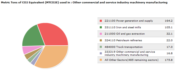
For the soda dispensing system itself, a generic model has been used : 333319 : Other Commercial and Service Industry Machinery Manufacturing. Here is a visual representation of the main sectors contributing to the total equivalent CO2 emission per million dollar :
Power generation, Iron and Steel mills, Oil and gas, Petroleum, Tranportation, Manufacturing : all this seems reasonable for a product like ours.
- Other concerns :
The fact that the producer's costs had to be estimated could potentially create a considerable difference in this analysis, because these costs are directly related to the amount of mtCO2e calculated per product lifetime. For example, if the production of 20lb of CO2 actually costed $0.5 instead of $5, the implied mtCO2e released would be 10 times less : 2.5 instead of the overwhelming 25 !
Team Members
Christy St. John: Administration, DFE (Eco-Manufacturing), Team Lead
Dan Murby: Executive Summary, Use Study, Bill of Materials
Elle Allen: DFMA Lead
Taryn Monteleone: FMEA Lead
Julien Locher: DFE Lead (EIOLCA), Bill of Materials Pictures
References
Dieter, George E., and Linda C. Schmidt. Engineering Design. 4th Edition. New York, NY: McGraw-Hill, 2009. Print.
[1] http://sodadispenserdepot.com/faqpage.html
[2] http://www.sodaparts.com/support/faq#7
[3] http://kk.org/cooltools/archives/1818
[4] http://www.instructables.com/id/DIY-Soda-Water-%26-Home-Carbonation---Pays-For-Itsel/
[5] http://www.geek.com/news/modding-your-sodastream-with-a-larger-co2-tank-1501061/
[6] "Beverage and Liquor Dispensing Systems | Wunderbar.com." Beverage and Liquor Dispensing Systems | Wunderbar.com. N.p., n.d. Web. 03 Feb. 2014.
[7] http://holtec.net/media/29015/Wunderbar.pdf