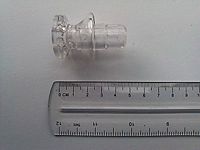
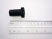
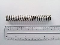
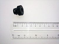
Retractable umbrella
From DDL Wiki
| Line 69: | Line 69: | ||
==Mechanical Function== | ==Mechanical Function== | ||
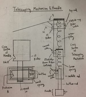
| - | [[Image:Telescoping Mechanism & Handle.jpg|thumb| | + | [[Image:Telescoping Mechanism & Handle.jpg|thumb|300px|right|Figure 2. Cross-Section of Telescoping Mechanism & Handle]] |
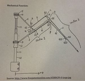
| - | [[Image:Umbrella Arm.jpg|thumb| | + | [[Image:Umbrella Arm.jpg|thumb|300px|left|Figure 3. Cross-Section of Umbrella Arm]] |
| - | + | <br> | |
The mechanical function of the umbrella consists of two portions: (1) Opening the umbrella and (2) Closing the umbrella. There are specialized terms used in this description. Please refer to the relevant drawings for a better understanding of what the specialized terms are referring to. The specialized terms are placed within quotations. | The mechanical function of the umbrella consists of two portions: (1) Opening the umbrella and (2) Closing the umbrella. There are specialized terms used in this description. Please refer to the relevant drawings for a better understanding of what the specialized terms are referring to. The specialized terms are placed within quotations. | ||
Revision as of 14:20, 23 September 2012
Executive Summary
Major Stakeholders and Their Needs
Four major stakeholders were identified in the life cycle of the umbrella: the consumer, the retailer, the manufacturer and the distributor. Each of them is described in detail in the following subsections.
Consumer
An umbrella is a product commonly used by people to refuge from rain and other environmental phenomena. Most people have had at least one umbrella in their lifetime, therefore consumer diversity was considered during the evaluation of their needs. The requirements of the consumer can be summarized as:
- Rigidity: the product needs to be able to support itself in the hands of the person using it.
- Portability: consumers want a product that they can carry around all day, they need a product that is compact and easy to carry.
- Appearance: the products should appeal the consumer.
- Low cost: as a product that users carry all day, umbrellas tend to be lost or forgotten often. A low cost device could be replaced more often, than an expensive one. In addition, many consumers would not want to spend a large amount of money in a commonly used object.
- Safety: umbrellas have many small components and outstanding elements, they need to be safe for people to use.
- Durability: consumers want a product that does not need replacement often
- Light-weight: commonly, consumers carry umbrellas all day with them, most would opt not to carry or use it if it is too heavy.
Retailer
The fact that umbrellas are commonly used object makes their market a competitive one. Retailers needs are focused on making their product profitable. The following list summarizes their needs:
- Appearance: the product needs to be appealing to the consumer to be competitive .
- Price: the product needs to have a reasonable price that will yield revenue.
- Reliability: the product needs to be reliable, since its reputation reflect on the name of the retailer.
- Safety: the product needs to be safe, since the retailer is responsible for accidents that an error in the product could cause.
Manufacturer
Manufacturers want to minimize the cost and time of manufacturing processes. The following list summarizes their needs:
- Simplicity of the design: manufacturers need a simple design with simple geometries
- Modularity of the design: manufacturers need a modular design that optimizes the processes of manufacture.
- Materials: low cost and non-toxic materials minimize the cost of the manufacture.
- Manufacturing process: low cost
- Storage: minimum the weight and overall dimensions make the object easier to store and transport.
Distributor
Distributors want to minimize the cost and time of distribution of the product. The following list summarizes their needs:
- Compact: the product needs to be easy to pack and able to survive distribution
- Modularity: the product needs to have modular replacement parts
- Storage: minimum the weight and overall dimensions make the object easier to store and transport.
Product History
Product Functionality and Use
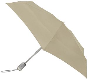
To open the umbrella, the user presses the button on the handle and allows it to extend and then expand fully. Then he or she holds the umbrella over her or his head, so as to prevent the elements from reaching her or him. To close the umbrella, the user pulls the rider down until it is locked back into the handle.
Mechanical Function
The mechanical function of the umbrella consists of two portions: (1) Opening the umbrella and (2) Closing the umbrella. There are specialized terms used in this description. Please refer to the relevant drawings for a better understanding of what the specialized terms are referring to. The specialized terms are placed within quotations.
Opening the Umbrella:
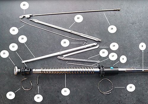
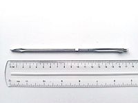
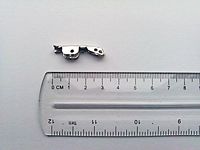
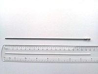
To open the umbrella, the button is pushed. This causes “protrusion A” to move out of “Hole A.” As a result, the “rider” is free to move away from the base. The “rider” moves away from the base and springs upwards because it is attached to the “top rod” via linkages “4” and “21.” The “top rod” is attached to the “upper spring,” which is attached to the “middle rod.” The “middle rod” is attached to the “lower spring,” which is attached to the “bottom rod.” As a result, the “rider” springs upwards away from the handle. Because the springs and rods are all interconnected, the whole telescoping mechanism also springs into its full length. During this, the “flatside-down rider latches” spring out to secure the telescoping mechanism and prevent it from recompression. The “flatside-up rider latch” also springs out but for a different purpose. This latch prevents the “rider” from leaving its terminal position.
During the extension of the telescoping mechanism, there is also another mechanism at work: “the umbrella arm mechanism.” The umbrella arm mechanism is divided into two sections. The umbrella is also folded into these two sections. As a result, the two sections have the length of umbrella when it is closed up. Specifically what happens is the following: As the “rider” moves up, “angle α” decreases which causes “section 1” to extend into the positive x direction. Component “5” pushes section 2 out but not as much as “section 1,” resulting in “section 2” extending outwards into the positive x direction also. The combined effort of all the arms extending the positive x (or positive r direction, radially) causes the umbrella to open up.
Note: The arms on our umbrella does not have component “61” and “62” that is shown in the diagram.
Closing the Umbrella:
When closing up, the user needs to push in the “flatside-up rider latch” to free the “rider” from being secured. Then user then needs to pull the “rider” towards the handle. This will require force since the user is going against the compressive force of the spring. As the umbrella moves down the three rods of the telescoping mechanism, it engages with the curved side of the “flatside-down rider latches.” This pushes the “flatside-down rider latches” inward and frees the rods of the telescoping mechanism. This allows the umbrella to be retracted. When the “rider” moves down into the handle, it locks with “protrusion A” and remains there in the closed state. On the other hand, “the umbrella arm mechanism” does the same thing as it does when “opening the umbrella” except it is in reverse.
Bill of Materials
Assembly List
Parts List
| Part Number | Name | Quantity | Mass, g | Function | Material | Manufacturing Process | Image |
|---|---|---|---|---|---|---|---|
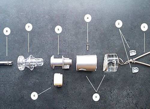
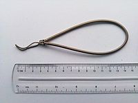
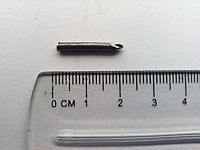
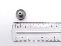
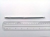
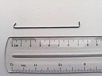
| 01 | Elastic Rope | 1 | 3 | Provides a convenient mode of carrying the umbrella when not in use | Rubber + Polyester | Cut from source rope and tied into loop shape | |
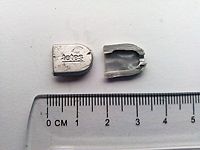
| 02 | Rope Clip | 1 | < 1 | Clips over tied end of elastic rope handle (part #01) to prevent fraying. Also the sight of brand logo | Plastic | Injection Molding | |
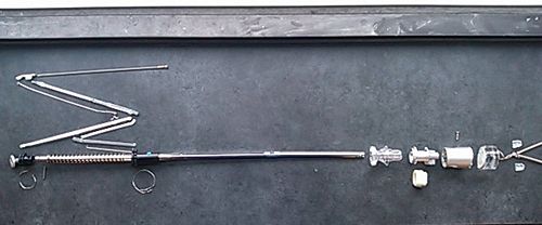
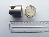
| 03 | Handle Mechanism Casing | 1 | 38 | To house release mechanism. Added weight and rigidity of clear cylindrical block enhances stability and strength | Plastic | Injection Molding | |
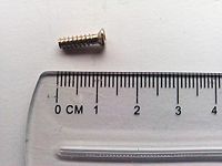
| 04 | Screw | 1 | < 1 | Attaches handle casing (03) to the anchor (05) and to the telescoping shaft (08) | Steel | Subtraction & Deformation | |
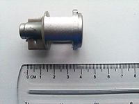
| 05 | Anchor | 1 | 4 | Houses release button (06) and handle spring (25). The shaft of the umbrella (08) fits into a slot at the bottom of this part. A small notch at the top of this component keeps the release button (06) and rider (07) in proper alignment. A hole near bottom of component is location where the screw (04) attaches this component to the handle mechanism casing (03) and also to the shaft. | Plastic | Injection Molding | |
| 06 | Release Button | 1 | 4 | Releases latch inside handle to allow shaft extension | Plastic | Injection Molding | |
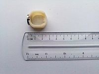
| 07 | Rider | 1 | 11 | Once pushed upward by user, activates arm mechanism | Acrylic | Injection Molding | |
| 08 | [Insert Name] | [Insert quantity] | [Insert mass] | [Insert function] | [Insert material] | [Insert Manufacturing process] | |
| 09 | [Insert Name] | [Insert quantity] | [Insert mass] | [Insert function] | [Insert material] | [Insert Manufacturing process] | |
| 10 | [Insert Name] | [Insert quantity] | [Insert mass] | [Insert function] | [Insert material] | [Insert Manufacturing process] | |
| 11 | [Insert Name] | [Insert quantity] | [Insert mass] | [Insert function] | [Insert material] | [Insert Manufacturing process] | |
| 12 | [Insert Name] | [Insert quantity] | [Insert mass] | [Insert function] | [Insert material] | [Insert Manufacturing process] | |
| 13 | [Insert Name] | [Insert quantity] | [Insert mass] | [Insert function] | [Insert material] | [Insert Manufacturing process] | |
| 14 | [Insert Name] | [Insert quantity] | [Insert mass] | [Insert function] | [Insert material] | [Insert Manufacturing process] | |
| 15 | [Insert Name] | [Insert quantity] | [Insert mass] | [Insert function] | [Insert material] | [Insert Manufacturing process] | |
| 16 | [Insert Name] | [Insert quantity] | [Insert mass] | [Insert function] | [Insert material] | [Insert Manufacturing process] | |
| 17 | [Insert Name] | [Insert quantity] | [Insert mass] | [Insert function] | [Insert material] | [Insert Manufacturing process] | |
| 18 | [Insert Name] | [Insert quantity] | [Insert mass] | [Insert function] | [Insert material] | [Insert Manufacturing process] | |
| 19 | [Insert Name] | [Insert quantity] | [Insert mass] | [Insert function] | [Insert material] | [Insert Manufacturing process] | |
| 20 | [Insert Name] | [Insert quantity] | [Insert mass] | [Insert function] | [Insert material] | [Insert Manufacturing process] | |
| 21 | [Insert Name] | [Insert quantity] | [Insert mass] | [Insert function] | [Insert material] | [Insert Manufacturing process] | |
| 22 | [Insert Name] | [Insert quantity] | [Insert mass] | [Insert function] | [Insert material] | [Insert Manufacturing process] | |
| 23 | [Insert Name] | [Insert quantity] | [Insert mass] | [Insert function] | [Insert material] | [Insert Manufacturing process] | |
| 24 | [Insert Name] | [Insert quantity] | [Insert mass] | [Insert function] | [Insert material] | [Insert Manufacturing process] | |
| 25 | [Insert Name] | [Insert quantity] | [Insert mass] | [Insert function] | [Insert material] | [Insert Manufacturing process] | |
| 26 | [Insert Name] | [Insert quantity] | [Insert mass] | [Insert function] | [Insert material] | [Insert Manufacturing process] |
Analysis
Detailed Product Analysis
Design for Manufacturing & Assembly (DFMA)
Manufacturing
Assembly
Failure Mode Effects and Analysis (FMEA)
| Item and Function | Failure Mode | Effects of Failure | S | Cause of Failure | O | Design Controls | D | RP N | Recommended Actions |
|---|---|---|---|---|---|---|---|---|---|
| [Item and Function] | [Failure Mode] | [Effects of Failure] | [S] | [Cause of Failure] | [O] | [Design Controls] | [D] | [RP N] | [Recommended Actions] |
| [Item and Function] | [Failure Mode] | [Effects of Failure] | [S] | [Cause of Failure] | [O] | [Design Controls] | [D] | [RP N] | [Recommended Actions] |
| [Item and Function] | [Failure Mode] | [Effects of Failure] | [S] | [Cause of Failure] | [O] | [Design Controls] | [D] | [RP N] | [Recommended Actions] |
| [Item and Function] | [Failure Mode] | [Effects of Failure] | [S] | [Cause of Failure] | [O] | [Design Controls] | [D] | [RP N] | [Recommended Actions] |
| [Item and Function] | [Failure Mode] | [Effects of Failure] | [S] | [Cause of Failure] | [O] | [Design Controls] | [D] | [RP N] | [Recommended Actions] |
| [Item and Function] | [Failure Mode] | [Effects of Failure] | [S] | [Cause of Failure] | [O] | [Design Controls] | [D] | [RP N] | [Recommended Actions] |
| [Item and Function] | [Failure Mode] | [Effects of Failure] | [S] | [Cause of Failure] | [O] | [Design Controls] | [D] | [RP N] | [Recommended Actions] |
| [Item and Function] | [Failure Mode] | [Effects of Failure] | [S] | [Cause of Failure] | [O] | [Design Controls] | [D] | [RP N] | [Recommended Actions] |
| [Item and Function] | [Failure Mode] | [Effects of Failure] | [S] | [Cause of Failure] | [O] | [Design Controls] | [D] | [RP N] | [Recommended Actions] |
| [Item and Function] | [Failure Mode] | [Effects of Failure] | [S] | [Cause of Failure] | [O] | [Design Controls] | [D] | [RP N] | [Recommended Actions] |
| [Item and Function] | [Failure Mode] | [Effects of Failure] | [S] | [Cause of Failure] | [O] | [Design Controls] | [D] | [RP N] | [Recommended Actions] |
| [Item and Function] | [Failure Mode] | [Effects of Failure] | [S] | [Cause of Failure] | [O] | [Design Controls] | [D] | [RP N] | [Recommended Actions] |
| [Item and Function] | [Failure Mode] | [Effects of Failure] | [S] | [Cause of Failure] | [O] | [Design Controls] | [D] | [RP N] | [Recommended Actions] |
| [Item and Function] | [Failure Mode] | [Effects of Failure] | [S] | [Cause of Failure] | [O] | [Design Controls] | [D] | [RP N] | [Recommended Actions] |
| [Item and Function] | [Failure Mode] | [Effects of Failure] | [S] | [Cause of Failure] | [O] | [Design Controls] | [D] | [RP N] | [Recommended Actions] |
| [Item and Function] | [Failure Mode] | [Effects of Failure] | [S] | [Cause of Failure] | [O] | [Design Controls] | [D] | [RP N] | [Recommended Actions] |
| [Item and Function] | [Failure Mode] | [Effects of Failure] | [S] | [Cause of Failure] | [O] | [Design Controls] | [D] | [RP N] | [Recommended Actions] |
| [Item and Function] | [Failure Mode] | [Effects of Failure] | [S] | [Cause of Failure] | [O] | [Design Controls] | [D] | [RP N] | [Recommended Actions] |
Design for Environment (DFE)
Energy Analysis
Green House Gases Analysis
Toxic Releases Analysis
Life Cycle Assessment (LCA)
DFE Analysis Conclusion
Team Member Roles
Lizmarie Comenencia: Team Leader
Conroy Brown: ???
David Carter: DFMA Leader
Dennis Ou: ???
Teja Shah: FMA Leader
Marcus Townsend: DFE Leader
References
1. Carnegie Mellon University Green Design Institute. (2012) Economic Input-Output Life Cycle Assessment (EIO-LCA) US 2002 (428) model [Internet], Available from: <http://www.eiolca.net/> [Accessed 15 September, 2012]
2. Dieter, George E., and Linda C. Schmidt. Engineering Design. 4th Edition. New York, NY: McGraw-Hill, 2009. 707-715. Print.
3. http://en.wikipedia.org/wiki/File:Parts_of_an_Umbrella.svg
