Ski boot walking attachment
From DDL Wiki
(→Failure Mode and Effects Analysis (FMEA)) |
|||
| Line 1: | Line 1: | ||
| + | =Executive Summary= | ||
| + | =Market Analysis= | ||
| + | =Design Documentation= | ||
| + | =Design Analysis= | ||
==Failure Mode and Effects Analysis (FMEA)== | ==Failure Mode and Effects Analysis (FMEA)== | ||
===Summary of Findings=== | ===Summary of Findings=== | ||
| Line 275: | Line 279: | ||
Image:Skiboot_EIOLCA_toxic_wasteM.jpg|'''Post End-usage Sector: Toxic Release per every $1M of Product Disposed''' | Image:Skiboot_EIOLCA_toxic_wasteM.jpg|'''Post End-usage Sector: Toxic Release per every $1M of Product Disposed''' | ||
</gallery> | </gallery> | ||
| + | |||
| + | =House of Quality= | ||
| + | =Mechanical Analysis= | ||
| + | =Prototype Documentation= | ||
| + | =Design Process= | ||
Revision as of 19:24, 9 December 2008
Contents |
Executive Summary
Market Analysis
Design Documentation
Design Analysis
Failure Mode and Effects Analysis (FMEA)
Summary of Findings
The two most likely failure modes center around material wear during use (e.g. walking surface) and fatigue/overstrain (e.g. attachment spring). The walking surface, just like the sole of any other footwear, will inevitably wear with use. However, if the user possesses reasonable observational skills, this failure is detectable provided the user knows it is a problem. As for spring failure, the detectability of this failure is unfortunately quite high, as the user must notice the device's failure to lock onto the ski boot during installation. Other minor failure modes are mentioned, though they involve material choices and qualities - factors which require extensive analysis during the design phase but which are largely set once the product is released for manufacture. No failure mode mentioned below should present a large problem except for high-frequency usage.
Detailed Findings
How to read the table: The table below shows several ways in which the ski boot walking attachment may fail. The item and function column states the major components and their purposes, the possible failure mode column includes the possible ways in which the components may not perform as they are intended to, the effects of failure column describes the consequences of failure, the causes of failure column explains the possible sources of failure, and the design controls column explains methods in which the chance of failure mode can be reduced. The S,O, and D columns stand for severity, occurrence, and detection respectively. Severity is a measure of the significance of the effects of failure. Occurrence is a measure of the likelihood that a component will fail. Detection is a measure of the ability to detect the flaw either during the manufacturing process or by implementing the proposed methods mentioned in design controls. Finally, RPN stands for risk priority number, which is a quantification of design risk. RPN is the product of S, O, and D. The recommended actions column details proposed methods that can reduce the risk priority number. The responsibility column shows a group or an individual who would be responsible for the recommended action. The actions taken column explains actions that have been executed. Finally, the updated risk priority number due to the corrective action is displayed.
| Item & Function | Failure Mode | Effects of Failure | S | Causes of Failure | O | Design Controls | D | RPN | Recommended Actions | Responsibility & Deadline | Actions Taken | S* | O* | D* | RPN* |
|---|---|---|---|---|---|---|---|---|---|---|---|---|---|---|---|
Connectors & Pins
| The pins get sheared | Product becomes unusable. One of the main supports that holds its structure fails | 8 | Excessive usage | 2 | Test Strength of pins | 1 | 16 | Add more connectors so that the weight is more distributed along the pins | Design Engineers | N/A | 8 | 1 | 1 | 8 |
| The connectors get sheared in half | Product becomes unusable. One of the main supports that holds its structure fails | 8 | Excessive usage | 2 | Test Strength of connectors | 2 | 32 | Design Engineers | N/A | 8 | 1 | 2 | 16
| ||
Soles
| Smoothed grips | Reduces traction | 7 | Excessive sliding actions | 1 | Test the durability of the rubber | 3 | 21 | Create deeper grooves | Design Engineers | N/A | 7 | 1 | 3 | 21 |
| Worn-out foam | Reduces step-smoothing effect | 3 | Long-term use | 5 | Do durability tests | 2 | 30 | Make sure foam is securely held in place | Design Engineers | N/A | 3 | 5 | 2 | 30
| |
Top Plates
| Brittle Fracture | Compromises structural integrity of the walking attachment | 6 | Excessive loads | 2 | Test strength of the plastic | 3 | 36 | Try different materials and choose the most practical one | Manufacturer | N/A | 6 | 1 | 3 | 18
|
Glue
| Sheared until separation occurs | Compromises structural integrity of the walking attachment | 5 | Sheared and dissolved glue | 2 | Test what solvents can dissolve the glue and the strength of the glue | 2 | 20 | Use a substance that is ideal to bond plastic with rubber | Assembler | N/A | 5 | 2 | 2 | 20
|
Metal Frame and Plastic Clip
| Brittle fracture of the plastic component | Product becomes unusable. The component that holds the ski boot with the attachment fails | 7 | Excessive force applied. Constant impacts | 2 | Test strength of plastic | 2 | 28 | Try different materials and choose the most practical one | Manufacturer | N/A | 7 | 1 | 2 | 14 |
| Sheared rivets | Product becomes unusable. Joints to fit the walking attachment into the boots fail | 7 | Excessive force and twisting motions applied | 2 | Test strength of rivets as joints | 1 | 14 | Increase the diameter of the rivets | Assembler | N/A | 7 | 1 | 1 | 7 | |
| Plastic deformation of the springs | Less degree of freedom for the clip to adjust. Will not have a flush fit with the boot | 6 | Excessive usage. Too much compression deformation | 2 | Determine the point of plastic deformation of the springs | 3 | 36 | Try different materials for springs and choose the most practical one | Design Engineers | N/A | 6 | 2 | 3 | 36 |
Any failures that jeopardize the functionality of the walking attachment and endanger the user would receive a severity score of an eight. For example, failures in connectors and pins would result in the walking attachment to be divided in half, which is inoperable at this point. If the failures occur while someone is walking, then he/she could very well be hurt. The smoothing of the rubber grips receive a seven because the system would still be operable, but it would no longer be safe to walk on especially on slippery surfaces like ice.
Occurrence and detection are typically rated very low (between two and three) because most of the components serve a simple purpose, contain almost no complexity in their geometry, and are visible without taking anything apart. Furthermore, the only components that would have a slightly more difficult time to notice when failing are the compression springs. Each spring is located inside a hollow cylindrical chamber that is part of the metal frame, but even if one spring fails fail, it would be noticeable because the metal the piece containing the spring would not be adjustable. The occurrence values are estimated by examining the material of each component, the purpose each component serves, and the complexity of its geometry. The scales that were used for rating the severity, occurrence of failure, and detection of failure can be found on page 708 and 709 of Engineering Design (Fourth Edition) by Dieter and Schmidt<ref>Dieter, George and Schmidt, Linda. "Engineering Design(Fourth Edition)." McGraw-Hill. NY, 2009.</ref>.
Design for X (DFX)
Design for X (DFX) analyzes a product to evaluate the efficiency of the product design from various perspectives. In this report, three major analyses are conducted on our final walking attachment design – Design for Manufacture (DFM), Design for Assembly (DFA), and Design for Environment (DFE). By conducting three types of DFX analyses, the overall efficiency of the product design during the manufacturing stage (DFM), assembly process (DFA), and post end-use impact to the environment (DFE) will be determined.
Design for Manufacture (DFM)
This design for manufacture analysis discusses how individual components of the walking attachment were designed in order to minimize the time and cost of the manufacturing process. The product design can be optimized for the manufacturing process through (1) reducing the number of components, (2) homogenizing the components, or (3) redesigning of the components. Reducing the number of components or homogenizing the components cuts the capital cost of production as fewer machines are required to manufacture the product. On the other hand, redesigning of the product aims to reduce the material cost per unit product by subtracting the unnecessary portions (dead weight) of the components from the original design. The following features of the final design contribute to the ease of manufacturing.
Symmetry
The walking attachment is identical for both the right and left boot. Because of this, the walking attachments can all be produced in the exact same way and they can simply be sold in pairs, without having to make sure there is one of each type in each pair. In addition to symmetry across the body, the walking attachment is, itself, symmetrical. If you cut the design down the middle from the front to back, it is a mirror image of itself. With this, the pieces of silicon and rubber on each side can be die stamped in the same way and that simplifies the manufacturing process.
Low Part Count
Because the final design contains very few parts, there are only a few manufacturing processes involved. We only need the rubber, silicon, and foam to be stamped, the entire top plate with toe piece can be made with two injection molding processes (one for the front and one for the rear), and the clip components, the links, and the folding rods can all be machined with relative ease. This is a pretty low number of manufacturing processes, and much of it can be done for a low price and in a small amount of time.
Easy Production
None of the processes listed above are incredibly time-consuming or costly and therefore manufacturing costs will remain relatively low. Each of the pieces production methods and advantages are listed below.
Top Plate
- The entire plate with toe piece can be made using injection molding allowing for a lightweight and robust design.
- Injection molding will waste little material and take a relatively low amount of time.
- Compared to other manufacturing processes, like machining, that could be used for this part, less material will be wasted, it will be faster, and at a higher production run, will cost less per unit.
Sole Components
- The sole components (the rubber, silicon, and foam) can all be die stamped.
- The production time will be very low.
- Although some material will be wasted, time saved and low input costs will keep the overall manufacturing costs low.
Clip Components
- The metal parts composing the clip can all be machined to specification with relative ease and little time.
- The metal pieces are all pretty simple, so machining will be easy and very few of them involve material removal.
- The plastic pieces on the clip can be made using injection molding.
- This allows for fast production and little material waste.
Design for Assembly (DFA)
A Design for Assembly analysis discusses how each component of the product was designed to minimize the time and cost of assembly. Efficient product design for assembly involves (1) simple configurations of the assembly and (2) ease of aligning the components. Simple configuration of the components prevents confusion and misplacement during the assembly process, while ease of aligning the components speeds up the assembly. The DFA on the main components of the walking attachment are provided below.
Sole
The sole is designed with a few pieces of rubber and foam embedded into two foam beds. All of these components are going to be die stamped, so the entirety of the assembly process will be arranging the pieces properly, and then gluing them together in the correct configuration. This must be done for the front and rear part of the sole. After these pieces are put together, the tread will be glued on to the bottom of the completed sole, and then the sole pieces themselves will be glued onto the front and rear top plates. Overall, the low number of parts and the simple arrangement were made for ease of assembly.
Top plate and Toe Piece
The top plate pieces themselves require no assembly since they each come as a single injection molded piece. In order to link the two halves together, the assembly worker must put the links in the appropriate slots, then slide the rods into the holes on the sides of the plate, and then simply cap the holes so the rod doesn't slide out. After that, the employee needs only to slide the rod through the rear plate, attach the clip to it, and then cap the ends. This linking design was made for very fast assembly because it only requires a few very easy steps.
Clip
The clip is by far the most complex part of the device for assembly. Although the assembly steps are somewhat difficult, there aren't that many parts so it doesn't take away from the overall low assembly time. The worker must take the large metal arc and rivet it to the connecting rod and then put the spring containment shell over the connecting rod. Once they put the spring inside, the cap needs to be attached to the end, and then the plastic clip itself needs to be screwed onto the metal arc. The clip is then completed and needs to be attached to the top plate to complete assembly of the device.
Design for Environment(DFE)
The design for environment analysis discusses how individual components of the walking attachment were designed in order to reduce the environmental impact of the product throughout its life-cycle. Design optimization of most products often puts more emphasis on DFM and DFA rather than on DFE, as reducing the time and cost of production would directly lead to greater profit. However, as environmental issues have come to draw more attentions from the public, the DFE analysis is becoming one of the significant aspects of product development that cannot be ignored.
Economic Input-Output Life Cycle Assessment (EIO-LCA) is often used as a common tool for conducting a DFE analysis on a product. EIO-LCA uses the following information as inputs - the product's purchase price and the most relevant sector to its manufacturing and end-usage. The EIO-LCA calculates how much environmental impact each of the manufacturing and the end-usage sectors creates from either producing or operating the amount of product(s) that is worth the input price of the simulation. The environmental impacts of the walking attachment calculated in this EIO-LCA include "Conventional Air Pollutants", "GHG Emission", and "Toxic Release".
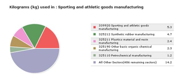
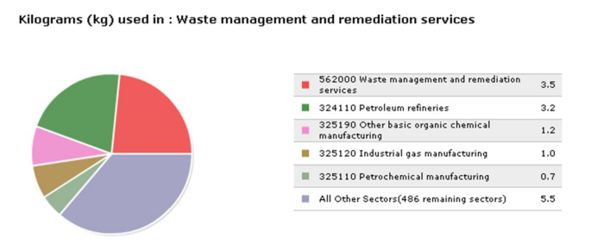
Practically, a DFE analysis using EIO-LCA compares environmental impacts from the manufacturing sector and operational (end-usage) sector in order to assess which stage of the product's life cycle has the most significant impact on the environment. However, it is quite apparent that the walking attachment does not create any significant environmental impact during use since the product does not require any fuel to operate and is designed for long-term use (rather than being a quick, disposable product). Therefore, the environmental impact from end-usage of the walking attachment is said to be negligible. As a result, the main focus of this analysis is on the product's environmental impact during the manufacturing stage and its end of life (EOL) stage. The sectors associated with each of those stages are the "Sporting and athletic goods manufacturing" sector (manufacturing) and the "Waste management and remediation services" sector (EOL) respectively. The "US Department of Commerce 1997 Purchase Price Model" is used in all of the EIO-LCA presented in the following section since it is the most recently built model available that uses consumer purchase price as its input. The model makes estimation of "per-unit-product" environmental impacts easier as the market price of the product is known.
More emphasis on environment-friendly manufacturing methods
The detailed EIO-LCA results are summarized in the following section (Summaries and Specifics of EIO-LCA).
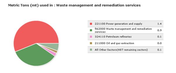
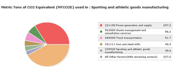
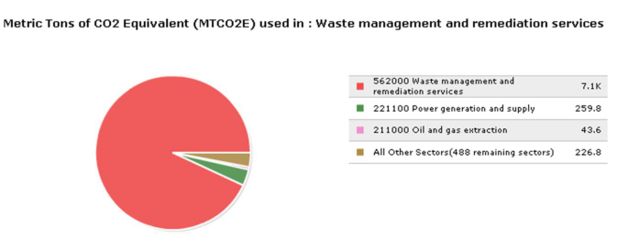
The simulation results show that manufacturing phase creates twice as much toxic release (30.1 kg/$1M) than disposal of the product does (15.1 kg/$1M). However, the relationship flips when discussing the amount of conventional pollutants emitted, as contributions from product disposal (2.5 metric tons/ $1M) nearly doubles that of manufacturing phase (1.3 metric tons/ $1M). What is more striking is that in terms of GHG emission, product disposal (7,600 MTCO2E/ $1M) has 10.5 times greater impact on the environment than the emission from the manufacturing sector (718 MTCO2E/ $1M). Thus, it is easy to conclude that in terms of environmental impact per cost, the most significant environmental impacts during the product's life cycle occurs in its post end-use (disposal) phase.
However, since the cost of manufacturing a unit of product and the cost of managing waste from a unit of product are not equal, environmental impact per unit of product (rather than per $1M economic input) needs to be determined. According to "THE PRICE OF SOLID WASTE MANAGEMENT SERVICES IN VERMONT" a study conducted by DSM Environmental Services, Inc. for the Vermont Department of Environmental Conservation (2005), managing 1 ton (1,000kg) of waste costs approximately $100. As the product analyzed in this DFE (WalkEZ) weighs about 1kg per unit, the waste management cost per unit is calculated to be around $0.10. The market price of the product is approximately $20 (200 times greater than the cost of waste management). Therefore, the simulated environmental impact per $1M from the EOL sector needs to be divided by a factor of 200 before being compared against the environmental impact per $1M from the manufacturing sector.
Combining those information, the manufacturing sector contributes approximately 0.602g of toxic release, 26.0g of conventional pollutants, and 0.0144 MTCO2E of GHG to the environment from producing one unit of the product. On the other hand, the EOL sector is responsible for 0.00151g of toxic release, 0.25g of conventional pollutants, and 0.00076MTCO2E of GHG per unit of product. Thus, it is apparent that the manufacturing sector is far more responsible for all the environmental impacts discussed here.
Major contributors to environmental impacts during the manufacturing phase
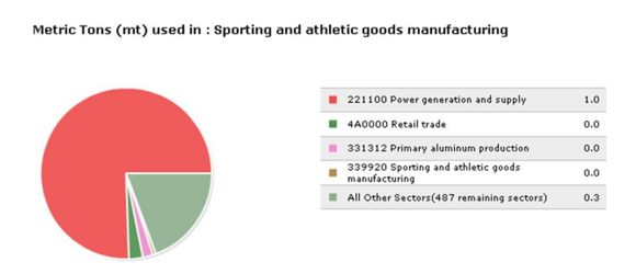
In manufacturing phase, power generation and supply are the biggest contributors to the sector's pollutants (77%) and GHG (29%) emissions. A more energy efficient manufacturing process would reduce those emissions.
More detailed results of EIO-LCA are summarized below.
EIO-LCA
- Model used:
- US Department of Commerce 1997 Purchase Price
- Walking Attachment Price ~ $20
- US Department of Commerce 1997 Purchase Price
- Manufacturing Sector:
- Industry Group: Misc. Manufacturing
- Industry Sector: #339920 - Sporting and athletic goods manufacturing
- Industry Group: Misc. Manufacturing
- End-use Sector:
- Industry Group: N/A - Negligible environmental impact from operations of the product
- Industry Group: N/A - Negligible environmental impact from operations of the product
- Post End-use (product after life) Sector:
- Industry Group: Management, Administrative, and Waste Services
- Industry Sector: #562000 - Waste management and remediation services
- Industry Group: Management, Administrative, and Waste Services
Comments on the industry sector selections
The manufacturing sector of the walking attachment is best represented by "Sporting and athletic goods manufacturing" sector. The example of the industries included in the sector include but are not limited to manufacturing of ski boots and various plastic athletic equipments. Given that the product is made of rubber materials (commonly used in several athletic equipments) and that the product's primary operation is for athletic/leisure purposes, "Sporting and athletic goods manufacturing" sector best describes the manufacturers of ski boot walking attachment - a very unique product.
