Window blinds
From DDL Wiki
(Difference between revisions)
| Line 223: | Line 223: | ||
|- | |- | ||
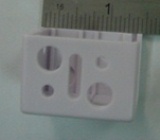
| - | | style="text-align: center;"| | + | | style="text-align: center;"|21 |
| - | | | + | | Lock Housing Pin |
| - | | style="text-align: center;"| | + | | style="text-align: center;"|1 |
| - | | style="text-align: center;"| | + | | style="text-align: center;"|<1 |
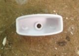
| - | | | + | | Fixes lock housing to main frame and acts as a holster for depressed locking gear |
| - | | | + | | Aluminum |
| - | | | + | | Extruding |
| + | |[[Image:blinds_21.jpg]] | ||
|- | |- | ||
|- | |- | ||
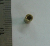
| - | | style="text-align: center;"| | + | | style="text-align: center;"|22 |
| - | | | + | | Locking Gear |
| - | | style="text-align: center;"| | + | | style="text-align: center;"|1 |
| - | | style="text-align: center;"| | + | | style="text-align: center;"|<1 |
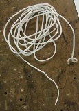
| - | | | + | | Catches string when slid against it, acts as the stopping mechanism |
| - | | | + | | Aluminum |
| - | | | + | | Extruding |
| + | |[[Image:blinds_22.jpg]] | ||
|- | |- | ||
|- | |- | ||
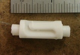
| - | | style="text-align: center;"| | + | | style="text-align: center;"|23 |
| - | | | + | | Locking Roller |
| - | | style="text-align: center;"| | + | | style="text-align: center;"|1 |
| - | | style="text-align: center;"| | + | | style="text-align: center;"|<1 |
| - | | | + | | Provides a smooth surface for the main string to slide against |
| - | | | + | | Aluminum |
| - | | | + | | Extruding |
| + | |[[Image:blinds_23.jpg]] | ||
|- | |- | ||
|- | |- | ||
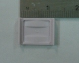
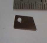
| - | | style="text-align: center;"| | + | | style="text-align: center;"|24 |
| - | | | + | | Lock Plate |
| - | | style="text-align: center;"| | + | | style="text-align: center;"|1 |
| - | | style="text-align: center;"| | + | | style="text-align: center;"|<1 |
| - | | | + | | Provides a smooth surface for the main string to slide against |
| - | | | + | | Aluminum |
| - | | | + | | Bending |
| + | |[[Image:blinds_24.jpg]] | ||
|- | |- | ||
|- | |- | ||
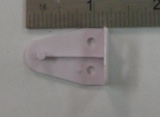
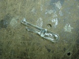
| - | | style="text-align: center;"| | + | | style="text-align: center;"|25 |
| - | | | + | | Twisting Rod Connector |
| - | | style="text-align: center;"| | + | | style="text-align: center;"|1 |
| - | | style="text-align: center;"| | + | | style="text-align: center;"|<1 |
| - | | | + | | Connects twisting rod to twisting rod hook |
| - | | | + | | Plastic |
| - | | | + | | Injection Molded |
| + | |[[Image:blinds_25.jpg]] | ||
|- | |- | ||
|- | |- | ||
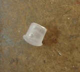
| - | | style="text-align: center;"| | + | | style="text-align: center;"|26 |
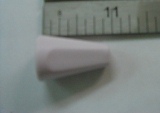
| - | | | + | | Twisting Rod Cap |
| - | | style="text-align: center;"| | + | | style="text-align: center;"|1 |
| - | | style="text-align: center;"| | + | | style="text-align: center;"|<1 |
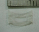
| - | | | + | | Closes the bottom end of the twisting rod |
| - | | | + | | Plastic |
| - | | | + | | Injection Molded |
| + | |[[Image:blinds_26.jpg]] | ||
|- | |- | ||
|- | |- | ||
| - | | style="text-align: center;"| | + | | style="text-align: center;"|27 |
| - | | | + | | Twisting Rod |
| - | | style="text-align: center;"| | + | | style="text-align: center;"|1 |
| - | | style="text-align: center;"| | + | | style="text-align: center;"|26 |
| - | | | + | | User control device, translates to blind tilt angle |
| - | | | + | | Plastic |
| - | | | + | | Injection Molded |
| + | |[[Image:blinds_27.jpg]] | ||
|- | |- | ||
|- | |- | ||
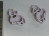
| - | | style="text-align: center;"| | + | | style="text-align: center;"|28 |
| - | | | + | | Twisting Rod Casing |
| - | | style="text-align: center;"| | + | | style="text-align: center;"|2 |
| - | | style="text-align: center;"| | + | | style="text-align: center;"|<1 |
| - | | | + | | Holds twisting gear and twisting screw in their proper locations, shaped to fit into main frame |
| - | | | + | | Plastic |
| - | | | + | | Injection Molded |
| + | |[[Image:blinds_28.jpg]] | ||
|- | |- | ||
|- | |- | ||
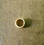
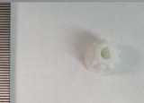
| - | | style="text-align: center;"| | + | | style="text-align: center;"|29 |
| - | | | + | | Twisting Gear |
| - | | style="text-align: center;"| | + | | style="text-align: center;"|1 |
| - | | style="text-align: center;"| | + | | style="text-align: center;"|<1 |
| - | | | + | | Holds inner rotating rod, and interacts with twisting screw |
| - | | | + | | Plastic |
| - | | | + | | Injection Molded |
| + | |[[Image:blinds_29.jpg]] | ||
|- | |- | ||
|- | |- | ||
| - | | style="text-align: center;"| | + | | style="text-align: center;"|30 |
| - | | | + | | Twisting screw |
| - | | style="text-align: center;"| | + | | style="text-align: center;"|1 |
| - | | style="text-align: center;"| | + | | style="text-align: center;"|<1 |
| - | | | + | | Converts user input turning to twisting gear rotations |
| - | | | + | | Plastic |
| - | | | + | | Injection Molded |
| + | |[[Image:blinds_30.jpg]] | ||
|- | |- | ||
|- | |- | ||
| - | | style="text-align: center;"| | + | | style="text-align: center;"|31 |
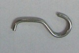
| - | | | + | | Twisting Rod Hook |
| - | | style="text-align: center;"| | + | | style="text-align: center;"|1 |
| - | | style="text-align: center;"| | + | | style="text-align: center;"|<1 |
| - | | | + | | Allows twisting rod to connect to twisting screw |
| - | | | + | | Aluminum |
| - | | | + | |Bending |
| + | |[[Image:blinds_31.jpg]] | ||
|- | |- | ||
|- | |- | ||
| - | | style="text-align: center;"| | + | | style="text-align: center;"|32 |
| - | | | + | | Hook Sleeve |
| - | | style="text-align: center;"| | + | | style="text-align: center;"|1 |
| - | | style="text-align: center;"| | + | | style="text-align: center;"|<1 |
| - | | | + | | Keeps twisting rod hook attached to twisting screw |
| - | | | + | | Plastic |
| - | | | + | | Extruding |
| + | |[[Image:blinds_32.jpg]] | ||
|- | |- | ||
|- | |- | ||
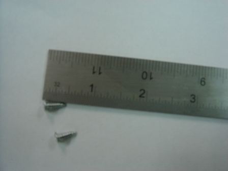
| - | | style="text-align: center;"| | + | | style="text-align: center;"|33 |
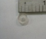
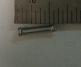
| - | | | + | | Rivets |
| - | | style="text-align: center;"| | + | | style="text-align: center;"|3 |
| - | | style="text-align: center;"| | + | | style="text-align: center;"|<1 |
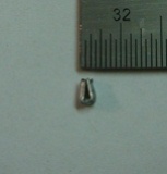
| - | | | + | |Holds twisting rod container together and locking roller together |
| - | | | + | | Aluminum |
| - | | | + | | Casting |
| + | |[[Image:blinds_33.jpg]] | ||
|- | |- | ||
|- | |- | ||
| - | | style="text-align: center;"| | + | | style="text-align: center;"|34 |
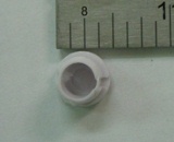
| - | | | + | | Rotating Rod Housing |
| - | | style="text-align: center;"| | + | | style="text-align: center;"|2 |
| - | | style="text-align: center;"| | + | | style="text-align: center;"|<1 |
| - | | | + | | Holds the Rotating Rod and the Main String Roller |
| - | | | + | | Plastic |
| - | | | + | | Injection Molded |
| - | | | + | |[[Image:blinds_34.jpg]] |
|- | |- | ||
| - | |||
| - | |||
| - | |||
| - | |||
| - | |||
| - | |||
| - | |||
| - | |||
|} | |} | ||
