Window blinds
From DDL Wiki
(→Bill of Materials) |
(→Bill of Materials) |
||
| Line 36: | Line 36: | ||
| Aluminum | | Aluminum | ||
| Heading, Thread Rolling (standard purchase part) | | Heading, Thread Rolling (standard purchase part) | ||
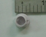
| - | |[[Image:blinds_1a.jpg| | + | |[[Image:blinds_1a.jpg|100px]] |
|- | |- | ||
|- | |- | ||
| Line 46: | Line 46: | ||
| Aluminum | | Aluminum | ||
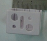
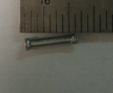
| Heading, Thread Rolling (standard purchase part) | | Heading, Thread Rolling (standard purchase part) | ||
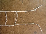
| - | |[[Image:blinds_2.jpg| | + | |[[Image:blinds_2.jpg|100px]] |
|- | |- | ||
|- | |- | ||
Revision as of 18:22, 3 February 2011
Contents |
Executive Summary
Major Stakeholders
Customer – Customers include those individuals or parties who actually purchase the blinds to fulfill a purpose. What they might be looking for in a set of blinds can vary from style and color to functionality and efficiency. Should there be any problems with the original set of blinds, parts should be easily replaceable. For consumers, it is all about an attractive, low-cost, and easy-to-maintain product.
User – Users in most cases will not be limited to the customer. Depending on where the blinds are installed, there could be 1 user or 1,000 users. A user will expect the blinds to be effective, sturdy and durable, and easy to use and clean.
Installer – The installer could be the customer, but in some cases could also be a professional who is familiar with home product installations. Of utmost importance in this case will be the compatibility of the blinds with standard tools and the minimization of steps for assembly.
Retailer – The retailer will be the first major post-production stop for a new set of blinds. For retailers, it is necessary that blinds not only cater to consumer needs, but do so in a way that gives retailers an incentive to sell them. Specifically, there should be sufficient variety in size, color, etc. to capture the needs of most customers, the blinds should fit into packaging that is easy to handle, store and ship, and the wholesale cost should be low enough that the retailer can make a profit.
Product Use
Product
Assembly
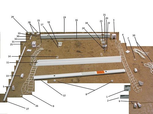
Bill of Materials
How the system functions mechanically
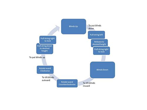
The packaged set of blinds can be split up into two separate phases: installation and use. During the installation phase the customer is supposed to install the wall mounts using the provided screws. Additionally the package provides an optional installation of the hold down mounts these mounts have pins that will hold the blinds in a lowered resting state. The hardware to install these mounts is included in the package. There are two ways for the customer to interact with the blinds after installation is complete.
The first way is to raise and lower the blinds according to preference. On the right side of the blinds there are two strings that can be pulled to disengage the lock or pulled to the right and released to reengage the lock. The locking mechanism consists of a gear that catches the string when it is released and pins it against another surface. The main string runs over a series of rollers in the main body, travel through the blinds and are tied off in the bottom bar. When the user pulls the string to adjust the height, the main string pulls or releases the bottom bar thereby raising or lowering the blinds.
The second way the customer can interact with the blinds is by controlling the tilt on the blinds by adjusting the twisting rod. By turning the rod clockwise the blinds rotate so that they are concave towards the customer. Rotating the rod counterclockwise produces an opposite effect. This is achieved through the translation of motion from the tilt rod to the inner rotating rod. When the twisting rod is turned, it turns a worm gear inside of the twisting rod casing. The worm gear turns a worm wheel that the inner rotating rod is attached to. On the rotating rod are two braces that can hold the ends of the ladder string. When the rotating rod turns, it makes one end of the ladder string pull up into the mainframe while releasing the other end. When this occurs, the blinds begin to tilt according to the customers input.
DFMA
The blinds that we dissected were cheaply purchased and because of this we know that they are massed produced. The assembly is relatively complicated with many interdependent working parts. After examining the manufacturing techniques used to produce the blinds we feel that the efficiency has been maximized. Most parts have been produced so that they can be used interchangeably, for example left and right parts do not matter. We saw that unnecessary material was removed from certain parts to reduce material usage and to make installation easier. We found that many parts snap together to make manufacturing time minimal and the same parts could be used for larger or smaller blinds. Minimal tools are required to manufacture and assemble these parts. Because these are inexpensive blinds that design was kept simple and fulfills its most basic purposes. The blinds use a lot of plastic parts and most of the plastic is the same. None of the parts manufactured seem to require tight tolerances.
Design for manufacturing guidelines
Minimize Part Count: Eliminate fasteners, part consolidation - only 3 rivets - wall mounts are interchangeable for left and right sides
Standardize Components: Take advantage of economies of scale & known component properties - wall mount had a lot of holes, reduced material, easy to install - many components come in pairs
Communize Product Line: Economies of scale and minimum training and equipment - parts snap together - larger blinds use similar parts
Standardize Design: Common dimensions for fewer tools and setups - only need rivet gun, bending machine
Keep Designs Simple: Simplest way to achieve needed functionality - easy access to screws
Multifunctional Parts: - wall mount can be left on right, many parts are interchangeable - lock house pin also supports lock gear
Ease of Fabrication: Choose materials easy to work with - product uses the same plastic material for many parts
Avoid Tight Tolerances: Causes exponential cost increases - no parts are machined
Take advantage of Special Process Properties: - wall mount, reduction of material
Design for Assembly guidelines
Use subassemblies: can be assembled and tested separately, can be outsource - not outsourced, but can be assembled in parallel
Mistake-Proof: unambiguous, unique assembly orientation - lock mechanism (roller, gear) are not dependent on orientation
Minimize Fasters: snap fits and part consolidation - there are a lot of snap fits - small sizes make it harder to assemble by hand
Minimize Part Count: Eliminate fasteners, part consolidation - only 3 rivets - wall mounts are interchangeable for left and right sides
Standardize Components: Take advantage of economies of scale & known component properties - wall mount had a lot of holes, reduced material, easy to install - many components come in pairs
Communize Product Line: Economies of scale and minimum training and equipment - parts snap together - larger blinds use similar parts
Standardize Design: Common dimensions for fewer tools and setups - only need rivet gun, bending machine
Keep Designs Simple: Simplest way to achieve needed functionality - easy access to screws
Multifunctional Parts: - wall mount can be left on right, many parts are interchangeable - lock house pin also supports lock gear
Ease of Fabrication: Choose materials easy to work with - product uses the same plastic material for many parts
Avoid Tight Tolerances: Causes exponential cost increases - no parts are machined
Take advantage of Special Process Properties: - wall mount, reduction of material
Minimize Handling: - rollers are difficult to snap in place by hand,
Maximize Assembly Compliance: - lock roller is chamfered - tilt housing is chamfered
Extra features:
- There are holes in the mounts that are suppose to aid in screwing into the wall
FMEA
A failure modes and effects analysis, or FMEA, is a procedure in product development where we analyze the potential failure modes within a system. Based on past experience with similar products we are able to identify potential failure modes and rate them based on the severity and frequency of their occurrence. After examining the use phase of the product we have identified important failure modes that should be considered in a redesign or a new design of the blinds. There are a few major failure potentials we identified. The product warns us multiple times about the potential of a child entangling themselves in the dangling cord. This is the most important failure as it is may jeopardize the health and well-being of a person. The label warns us that the cord and form a loop and become wrapped around a child’s neck resulting in death. This is something that must occur with some frequency for the warning labels to be so clear. Other failure modes we identified deal with the proper functionality of the blinds as they may be raised unevenly resulting in a bad look, or the blinds getting bent out of shape and fail in blocking out sunlight or providing privacy. If the tilt wand breaks off then the blinds will not be operational in blocking out or letting in sunlight. Finally, if the ladder-like string which holds the individual blinds was to be cut then the entire set of blinds would fall apart and be non-operational.
Table missing
DFE
Team Member Roles
Min-Qiang Chan-Manufacturing and Assembly
Laura Gurwitz-Team Leader
Kory McDonald-Safety
Francisco Santiago-Environment
