From DDL Wiki
Executive Summary
Major Stakeholders
Customer – Customers include those individuals or parties who actually purchase the blinds to fulfill a purpose. What they might be looking for in a set of blinds can vary from style and color to functionality and efficiency. Should there be any problems with the original set of blinds, parts should be easily replaceable. For consumers, it is all about an attractive, low-cost, and easy-to-maintain product.
User – Users in most cases will not be limited to the customer. Depending on where the blinds are installed, there could be 1 user or 1,000 users. A user will expect the blinds to be effective, sturdy and durable, and easy to use and clean.
Installer – The installer could be the customer, but in some cases could also be a professional who is familiar with home product installations. Of utmost importance in this case will be the compatibility of the blinds with standard tools and the minimization of steps for assembly.
Retailer – The retailer will be the first major post-production stop for a new set of blinds. For retailers, it is necessary that blinds not only cater to consumer needs, but do so in a way that gives retailers an incentive to sell them. Specifically, there should be sufficient variety in size, color, etc. to capture the needs of most customers, the blinds should fit into packaging that is easy to handle, store and ship, and the wholesale cost should be low enough that the retailer can make a profit.
Product Use
Assembly and Bill of Materials
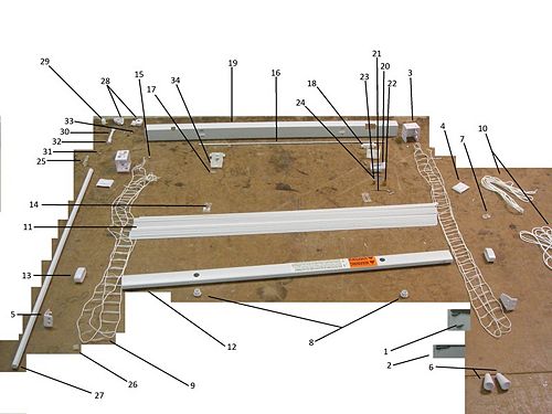
| Part Number | Name | Qty. | Weight (g) | Function | Material | Manufacturing Process | Image |
|
| 1
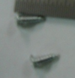
| 7/16 Screw
| 2
| <1
| Attach wall mount to wall
| Aluminum
| Heading, Thread Rolling
| 
|
| 2
| 7/8 Screw
| 12
| <1
| Attach wall mount to wall
| Aluminum
| Heading, Thread Rolling
| 
|
| 3
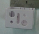
| Wall Mount
| 2
| 7
| Offers surface for blinds to rest on the wall
| Plastic
| Injection Molded
| 
|
| 4
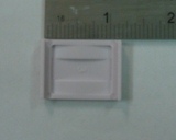
| Mount Lock
| 2
| <1
| Keeps blinds in the mount
| Plastic
| Injection Molded
| 
|
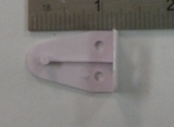
| 5
| Optional Hold Down Bracket
| 2
| <1
| Holds blinds in fixed setting (down)
| Plastic
| Injection Molded
| 
|
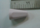
| 6
| Knot Cover
| 2
| <1
| Covers the knots at the main string ends and offers the user a gripping location
| Plastic
| Injection Molded
| 
|
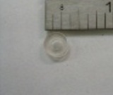
| 7
| Beads
| 2
| <1
| Allows user to set lowest blind setting
| Plastic
| Injection Molded
| 
|
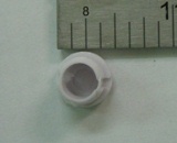
| 8
| String Plugs
| 2
| <1
| Plugs the main string insertion hole
| Plastic
| Injection Molded
| 
|
| 9
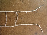
| Ladder String
| 2
| <1
| Contains equally spaced rungs to hold blinds
| Nylon
| Weaving
| 
|
| 10
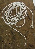
| Main String
| 2
| 3
| Control mechanism for blind height
| Nylon
| Weaving
| 
|
| 11
| Blinds
| 49
| 7
| Directly affects amount of light and privacy
| Plastic
| Extruding, Stamping
| 
|
| 12
| Bottom Bar
| 1
| 92
| Contains excess ladder string, acts as a weight for lowering the blinds
| Plastic
| Extruding
| 
|
| 13
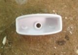
| Bottom Bar End
| 2
| <1
| Covers ends of bottom bar, has hole for optional hold down bracket
| Plastic
| Injection Molded
| 
|
| 14
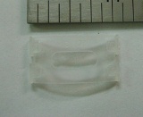
| String Brace
| 2
| <1
| Fixes ladder string in place at the top of the blinds
| Plastic
| Injection Molded
| 
|
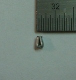
| 15
| Ladder String Stopper
| 4
| <1
| Gives ladder string a way to stay attached to the main frame
| Aluminum
| Extruding, Bending
| 
|
| 16
| Inner Rotating Rod
| 1
| 23
| Holds main frame components in place, controls tilt of blinds
| Aluminum
| Extruding, Stamping
| 
|
| 17
| String Roller
| 2
| <1
| Provides a smooth surface for the main string to slide against
| Aluminum
| Extruding
| 
|
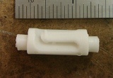
| 18
| Ladder String Holder
| 2
| <1
| Holds ladder string in place, allows for tilting
| Plastic
| Injection Molded
| 
|
| 19
| Main Frame
| 1
| 133
| Holds both raising and tilting components
| Plastic
| Injection Molded
| 
|
| 20
| Lock Housing
| 1
| <1
| Holds the locking mechanism
| Plastic
| Injection Molded
| 
|
| 21
| Lock Housing Pin
| 1
| <1
| Fixes lock housing to main frame and acts as a holster for depressed locking gear
| Aluminum
| Extruding
| 
|
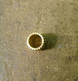
| 22
| Locking Gear
| 1
| <1
| Catches string when slid against it, acts as the stopping mechanism
| Aluminum
| Extruding
| 
|
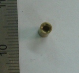
| 23
| Locking Roller
| 1
| <1
| Provides a smooth surface for the main string to slide against
| Aluminum
| Extruding
| 
|
| 24
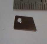
| Lock Plate
| 1
| <1
| Provides a smooth surface for the main string to slide against
| Aluminum
| Bending
| 
|
| 25
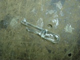
| Twisting Rod Connector
| 1
| <1
| Connects twisting rod to twisting rod hook
| Plastic
| Injection Molded
| 
|
| 26
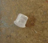
| Twisting Rod Cap
| 1
| <1
| Closes the bottom end of the twisting rod
| Plastic
| Injection Molded
| 
|
| 27
| Twisting Rod
| 1
| 26
| User control device, translates to blind tilt angle
| Plastic
| Injection Molded
| 
|
| 28
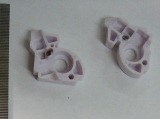
| Twisting Rod Casing
| 2
| <1
| Holds twisting gear and twisting screw in their proper locations, shaped to fit into main frame
| Plastic
| Injection Molded
| 
|
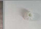
| 29
| Twisting Gear
| 1
| <1
| Holds inner rotating rod, and interacts with twisting screw
| Plastic
| Injection Molded
| 
|
| 30
| Twisting screw
| 1
| <1
| Converts user input turning to twisting gear rotations
| Plastic
| Injection Molded
| 
|
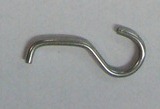
| 31
| Twisting Rod Hook
| 1
| <1
| Allows twisting rod to connect to twisting screw
| Aluminum
| Bending
| 
|
| 32
| Hook Sleeve
| 1
| <1
| Keeps twisting rod hook attached to twisting screw
| Plastic
| Extruding
| 
|
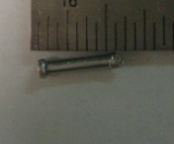
| 33
| Rivets
| 3
| <1
| Holds twisting rod container together and locking roller together
| Aluminum
| Casting
| 
|
| 34
| Rotating Rod Housing
| 2
| <1
| Holds the Rotating Rod and the Main String Roller
| Plastic
| Injection Molded
| 
|
DFMA
FMEA
DFE
Team Member Roles
References


