Staple gun
From DDL Wiki
This article was contributed as part of a design project for the course 24-441 Engineering Design in the spring semester of 2007 at Carnegie Mellon University.
A staple gun is a powerful device used to drive heavy duty staples into a material. This tool is significantly more powerful than a traditional stapler, and is also much faster and more efficient to use than a hammer and nails. For this reason, a staple gun is a commonly used tool in almost every place from construction to decoration.
Our goal is to make an improvement to this product based on our analysis. The analysis will include a review of the function of a staple gun, its uses, how it works, the many parts involved inside, as well as the design ideas that went into this product. All of these will be considered when coming up with improvements for this product.
The staple gun is used to fasten one material to another quickly and efficiently. In a typical use scenario a force is applied by hand to preload two metal bars which act as a spring. When the angle is great enough, the bars are released, driving a metal shaft downward, which in turn projects a staple into the material. The result is a staple firmly inserted into the material, and a very slight recoil. Other scenarios may include the staple gun being used in hard to reach or tight corners, by a user with weak or small hands, or incorrectly as a way of launching staples at people or objects. All of these uses will need to be considered when improving this product.
There are 22 parts or assemblies that make up this product. To find their detailed descriptions and functions, please see the Parts List below. There are also many features of these parts that are designed in order to improve the overall product. There are various grooves and guides to make assembly easier, bolts that require specialized tools to prevent users from disassembling it, two bars instead of one for easy stamping and manufacturing, comfortable grips for ease of use, and many more. The various designs found on the parts of this product improve its efficiency, improve user satisfaction, and reduce the costs associated with manufacturing.
The dissection and analysis of this product will be taken into account during the redesign of the product. The goal is to make an improvement that will make this product easier and more desirable for a consumer to use.

Contents |
Group 3
- Kristine Falletta
- Kacy Hess
- Galen Mullins
- Josh Schmieder
Product Analysis
Before we can make improvements to our staple gun, we must analyze our product to determine what advantages and disadvantages it currently has. In order to assess the traits of our staple gun we thought about what the function of the staple gun was, the different scenarios in which it might be used, who might use it, and what is required to operate it. Finally, we had a typical user test it and noted the steps that he took when operating it. Through all our testing we have discovered that our staple gun has many advantages. It is very sturdy and can withstand repeated use and abuse. The only requirment to make it work is an applied force on the handle making it simple, intuitive, and easy to use. Despite having a number of advantages, however, there are still many annoyances related to the staple gun that could be improved. For example, it is large and unwieldy which makes it difficult to carry on your person and even more difficult to fit into small spaces where a staple might be needed. Furthermore, it requires quite a bit of force to unload a staple so people with small or weak hands, or even just someone trying to use it in an odd position, may have difficulty firing it. There is also no safety on the staple gun to prevent people from accidentally firing it or misusing it to shoot staples across the room. The following sections give more detail about the general functions of the product, advantages and disadvantages, and how the product is typically used.
Function/Purpose
The function of the product is to fasten materials together using staples. This product is meant to be used to hang items from surfaces (such as walls, ceilings, etc.), attach one item to another, and other similar actions. It can also be used to shoot staples at targets, though this is not an intended use.
Inputs/Outputs
In order to use the staple gun both a force and a material are needed. The staples must be properly loaded in the gun, after which the proper force must be applied to the handle (generally created by the squeezing of a hand). This results in a staple projectile (typically into a surface) and recoil from the handle.
Typical Use Scenario
We asked a typical user to try to use our product and documented the steps he took while attaching a piece of wood to a corkboard.
1. Picked up the staple gun and placed hand on handle
2. Positioned material (wood) with empty hand against item to be fastened to (corkboard)
3. Positioned gun against the wood
4. Squeezed handled to release staple
5. Removed gun and checked to see if the materials were fastened together
6. No staple was present so repeated steps 2-5
7. When no staple was present again, located reloading place for staples to check for staples
8. Removed slider on bottom of gun and check for staples
9. When no staples were present, found staples and attempted to insert them
10. Positioned staples over extruded part of staple loader and tried to close the gun
11. When the slider did not close, repositioned staples inside gun and closed slider successfully
12. Repeated steps 2-5
13. Found that staple had successfully attached the two materials
Note: May have to unlock staple gun or adjust staple power before use. Do not always have to insert new staples.
Intended Use/Limitations/Annoyances
As previously stated, the intended function of this product is to fasten materials together by shooting a staple through them. Other features that are used to enhance this function include the ability to lock the handle for more compact storage and/or safety reasons, adjustable power so that the user may staple with more or less force, as well as a loading mechanism. Staples may be loaded by sliding the bottom of the stapler out, inserting the staples into the open compartment, then sliding and locking the bottom of the stapler back in place.
There are a number of limitations and annoyances with this design. With regards to typical use, a great amount of force is required to squeeze the handle for shooting staples. It is exceptionally difficult to exert enough force to release a staple when one is stretched out over and long distance and trying to press against a surface at the same time. This is true even if the staple gun is on the low power, which, as it turns out, is difficult to adjust. It is nearly impossible to reach into small or tight places due to the size of and configuration of the staple gun. Safety and storage are also of concern. There is no safety lock currently installed on the staple gun. (Note: the lock that is already on the stapler is intended for storage purposes, and does not prevent the accidental trigger of the staple gun.) Also, the size is awkward and difficult to store or carry on your person when also using other tools. Finally, the window showing the user if there are staples in the staple gun and what size those staples are is not very big and the user may not notice right away that the staple gun is not loaded. This could be very frustrating if the user lined up their materials just right and then lost that because they had to let go and reload the staple gun.
Some of the advantages of this design are its sturdiness and solid weight, the easy loading mechanism (once the process is known), the comfortable grip, it's compatibility with different sized staples and the availability of a power adjustment option (which also makes the product seem higher in quality/more advanced).
Different Users / Use Scenarios
There are some instances that may occur in which the user might find this product difficult to use. Should the force to dispense staples be too high, people with small or weak hands would not be able to use it. On the other end of the spectrum, people with large hands may not be able to fit their hands in the handle. Another scenerio that could occur is the desire to use the staple gun improperly (e.g. shooting staples at one another). Finally, people who need to fit staples in small, tight places may not be able to get the gun into those places.
Product Dissection
The product dissection is a very important part of our project. By carefully removing parts one at a time we can determine the function of each individual part and how the staple gun works as a whole. The videos and pictures below show the steps the staple gun goes through when projecting a staple and the how the individual pieces fit in together and what their function is.
How it works
This staple gun is made to work in a very simple manner. The user inputs a force by pushing down on the handle. This in turn, lifts up the loader which has two hooks that pull up on the two tension bars. The lower tension bar lifts up the staple piston as it rises. When the tension bars are bent back far enough they slip off the hooks on the loader and snap downwards forcing the staple pistion into the next staple sitting in the queue. As the handle is released by the user, the reloader springs push the loader down and, because of the curved edges on the hooks of the loader, the loader hooks itself over the tension bars again and is ready to use again.
The following is a link to a video of how the staple gun works: Staple Gun in Motion
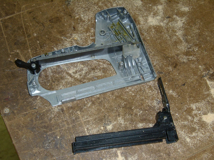
Disassembly Procedure

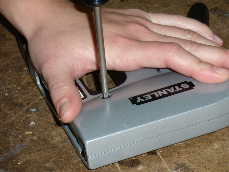
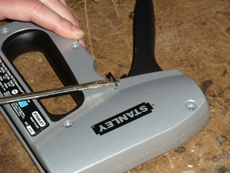
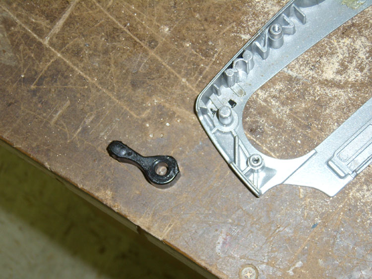
The first challenge we faced in disassembling the staple gun was removing the four hexstar screws (parts 001) that secured the top chassis to the bottom. Each screw had a cylindrical protrusion in the center that hindered regular hexstar screwdrivers from being effective. Thus, we drilled a small hole in a hexstar screwdriver so that it could slip over the protrusion on the screws. Next, we were able to pry off the safety storage lock (part 002) and remove the top chassis. (part 003)
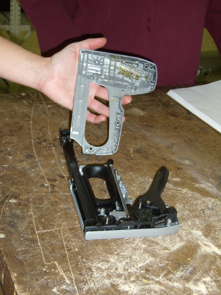
After removing the top chassis, we were able to see that the most of the remaining of the parts could be easily removed by simply pulling them off of the bottom chassis.
First, we removed the inner grip (part 004). Next, we carefully removed parts 005-012. (see parts list below) See [this video] to watch us removing each of these parts.
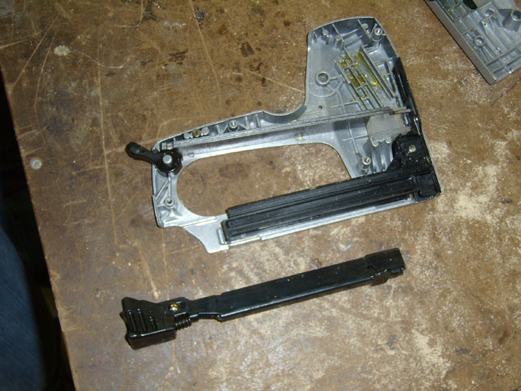
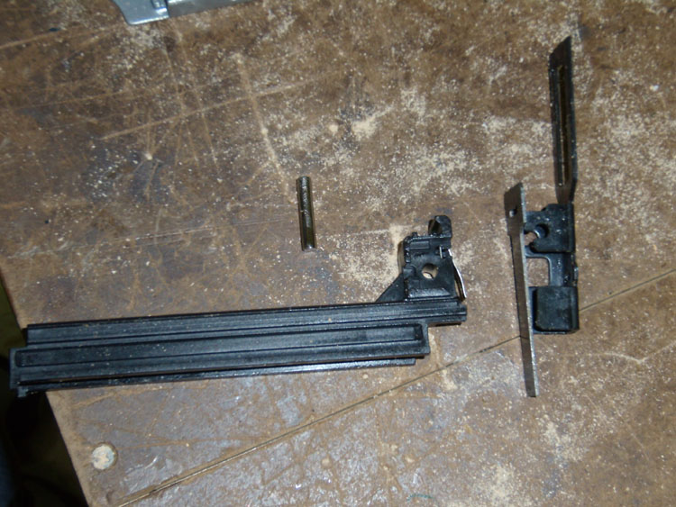
After that, we were able to slide the staple loader out (part 013), and lift the staple queue, staple piston, staple piston guide, and small pin out together. (parts 014, 015, 016, and 022, respectively) We separated these parts after removing them from the chassis.
Finally, the tension bars, power lever, and spacer were all easily lifted out of the chassis.
Documentation
Parts List
| Part # | Part name | QTY | Function | Wt.(kg.) | Material* | Process* | Photo |
|---|---|---|---|---|---|---|---|
| 001 | Hexstar screw | 4 | Holds opposite sides of chassis together, unique design prevents it from being taken apart | <.001 | N/A | N/A | 
|
| 002 | Safety Storage Lock | 1 | Holds down trigger handle for smaller profile during storage | <.001 | aluminum | Exrusion - bent? | 
|
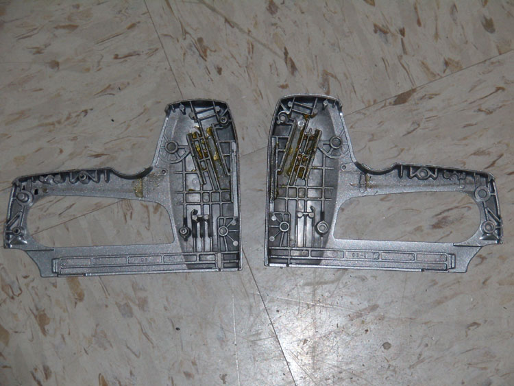
| 003 | Chassis/top | 1 | Provides support and protection for components, screws enter from this side | .117 | aluminum | Casting | 
|
| 004 | Inner Grip | 1 | Provides comfortable place to hold onto staple gun | .016 | plastic/black | Injection Molding | 
|
| 005 | Reloader spring | 2 | Pushes on handle to return it to it's upright position | <.001 | N/A | N/A | 
|
| 006 | Spring Holder | 1 | Anchors the reloader springs | .002 | Plastic/Black | Injection Molding | 
|
| 007 | Loader | 1 | Greased plastic latch attached to halde which catches and pulls back the tensions bars until it reaches the release point where it's curved shape releases the bars suddenly | 0.024 | plastic | Injection Molding | 
|
| 008 | Handle | 1 | A metal bar that connects to the loader and transfers the force input of the user by proxy of the loader to the tension bars | .071 | steel | Stamping | 
|
| 009 | Handle Grip | 1 | A plastic cover for the handle which allows the user a more comfortable hold when using the stapler | - | plastic/black | Injection Molding | 
|
| 010 | Handle grip screw | 4 | Phillips screw which attaches Handle Grip to Handle | # | N/A | N/A | 
|
| 011 | Pin (Large) | 1 | Acts as a pivot point for the handle, anchoring it to the chassis | 0.005 | steel | Extrusion | 
|
| 012 | Pin (Medium) | 2 | Acts as guide for handle motion | 0.003 | steel | Extrusion | 
|
| 013 | Stapler Loader | 1 | (Assembly) Pushes the staples into place to be launched | 0.041 | (Assembly-plastic/metal) | Injection Molding/Stamping | |
| 014 | Staple Queue | 1 | Provides location for staple storage and holds them in place until they are to be launched | 0.027 | (Assembly - plastic) | Injection Molding | 
|
| 015 | Staple Piston | 1 | powered by the tension bars this piece of metal knocks the stapler out of the gun and into the material | 0.007 | steel | Stamping | 
|
| 016 | Staple Piston Guide | 1 | attaches to piston and provides support and railings to guide it along its path | 0.023 | steel | Stamping | 
|
| 017 | tension bar (lower) | 1 | Stores energy for driving staple piston using the spring properties of a beam | 0.050 | steel | Stamping | |
| 018 | tension bar (upper) | 1 | Stores energy for driving staple piston using the spring properties of a beam. Is shorter than lower bar | 0.048 | steel | Stamping | |
| 019 | power lever | 1 | Adjusts the level of pretension in the bar | 0.003 | plastic-black | Injection Molding | 
|
| 020 | Chassis (bottom) | 1 | Provides support and protection for components | .134 | aluminum | Casting | 
|
| 021 | Spacer | 1 | Acts as a stop to prevent the tension bar from going to far, absorbs impact from tension bar when staple gun is fired | 0.005 | plastic-transparent | Injection Molding | 
|
| 022 | Pin (Small) | 1 | Provides a point load to tension bars which holds them in place and provides a pretension condition | 0.003 | steel | Extrusion | 
|
* Disclaimer: Materials and Manufacturing Processes are not within our area of expertise. Therefore, all materials and processes are our best educated guesses based on our knowledge and research.
Design Considerations
A proper product analysis includes a careful study of the product's design. This analysis includes two major categories: Design for 'X' and Failure Mode Event Analysis or FMEA. The first involves the analysis of the parts of the product in order to determine why each one is made the way it is. By working backwards, we can try and determine what designers considered when making the part, and how they better designed the part for assembly, disassembly, the environment, manufacturing, reliability, safety, and usability. When we improve our product, we will take these same things into consideration and try to integrate our improvement into the current design. The other aspect, FMEA, involves the determination of the ways in which the product may fail. A careful analysis will reveal what could fail, why and and how it would fail, as well as the likelyhood of failure and how it can be avoided.
A careful list of all of our determinations for both Design for 'X' and FMEA has been made below.
Design for 'X'
In the design process for the product there are many aspects of this product that need to be considered. These include designing for ease of assembly, for efficency in manufacturing, for ease of repair, for reliability, user safety, and enivromental impact. For each of these we went through the different ways this product had been designed with each aspect in mind. We listed the most notable occurances observed in the design during dissection below.
Design for Assembly
- Chassis contains ridges to help guide pieces in and align the top with the bottom
- Tapered screw guides in chassis ensure quick and easy alignment of screws
- Parts are made to fit together or slide into one another eliminating the need for screws
Design for Disassembly
- Hex bolts with circular protrusion in the middle require special tools making this product difficult for users to disassemble; done for practical and safety reasons
- Easy disassembly by manufacturer could lead to reuse of old spare parts
Design for Environment
- Materials are not biodegradable, but they are not toxic (environmentally neutral)
- Aluminum is environmentally costly to make, but very recyclable
- Generally speaking, product is straightforward enough such that environmental factors were not a primary concern, hence the limited considerations in this area
Design for Manufacture
- Spring made of two bars instead of one thick one to making them easier to stamp
- All pparts can be manufactured with relatively simple, common, and straightforward processes
- Most parts are made by injection molding or stamping
Design for Reliability
- Product is made with a life time amount of grease to eliminate the need to open it
- Parts are very sturdy (ie, can drop without consequences)
- Ratio of force to yield stress is minimal so the parts an withstand repeated use
- Product is rust proof: parts are made out of aluminum, stainless steel, and plastic
- User cannot easily open the product, so parts are less likely to be tampered with
Design for Safety
- User cannot disassemble easily
- If it is disassembled, no parts will fly out at or be hazardous to one's health
- The staple gun is slightly difficult to shoot, thus, it will not randomly fire
Design for Usability
- Plastic grips designed for comfort
- Product is intuitive and easy to use (point and sqeeze)
- Flaw: staple loading process is slightly counter-intuitive (despite advertising)
- Loading process is very easy once the user knows how
- Power adjuster to accomadate different types of users (could be improved however)
- Staple comes out at the top end of the gun making it easy to line up where the staple should be place
Failure Mode Event Analysis (FMEA)
FMEA involves the analysis of the various parts of a product to find the most likely failures, their associated causes, and how to avoid them. Below we have listed some of the failure modes of a staple gun, and created a chart to show the in depth analysis of each part.
- Wearing down of plastic hooks (loader's hooks) would lead to spring slipping too soon and not producing enough power to fire staple
- Grease may be depleted if the gun is used in rainy conditions
- Reloader springs are not as heafty as other parts and may not last for the life time of the gun
Sample FMEA chart. S refers to Severity of failure, O refers to the probability of Occurance, and D refers to the ease of Detection.
| Item & Function | Failure Mode | Effects of Failure | S | Causes of Failure | O | Design Controls | D | RPN |
|---|---|---|---|---|---|---|---|---|
Loader
| Wearing down of hooks on loader | Impossible to pull back the tension bars, product ceases to function. | 9 | Damage occurs through use over products lifetime | 2 | Stress test of staple gun through several thousand uses | 6 | 108
|
Grease
| Loss of grease | The loss of grease would make the device harder to use and cause increased wear on moving components | 7 | Use through lifetime or through adverse enviromental conditions (water) | 2 | Test device after applications through water and through stress testing | 6 | 84 |
Reloader Spring
| Mechanical Failure | Handle will need to be returned to ready position by user between each use | 2 | Through wear spring may break | 2 | Test springs to ensure lifetime | 2 | 8 |
This staple gun seems to be very well designed. There were a few other failure modes that we thought of, but did not believe that they would be a problem unless there were some defect in the manufacturing process. The chasis and handle are very sturdy and would be able to withstand a good amount of use and abuse including dropping the staple gun. The parts inside the staple gun are held in place very well and would not become lose if the staple gun were dropped. The two metal tension bars also would not be an issue. The deflection that the bars incur during loading is quite small and does not come near the plastic deformation of the bars. These bars should easily last the lifetime of the staple gun. In short, the staple gun is not in any real danger of failing in normal and possibly even improper use conditions.
Numerical Analysis
In order to better understand how the staple gun works and what the inputs and outputs of the product are we completed a free body diagram and did a numerical analysis on the tension bars. The detailed analysis is shown on the Staple gun numerical analysis page.
